D4NS-1AF Omron, D4NS-1AF Datasheet - Page 9
D4NS-1AF
Manufacturer Part Number
D4NS-1AF
Description
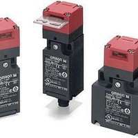
Basic / Snap Action / Limit Switches Plastic NC1NO type Interlock
Manufacturer
Omron
Type
Safety Door Key Switchr
Specifications of D4NS-1AF
Contact Form
1 NC / 1 NO
Contact Rating
10 Amps at 120 VoltsAC, 240 VoltsAC
Actuator
Key
Contact Voltage Ac Max
400V
Contact Voltage Dc Max
250V
Contact Current Ac Max
6A
Switch Terminals
Screw
Svhc
No SVHC (15-Dec-2010)
Approval Bodies
EN60947-5-1, IEC 947-5-1, EN1088, EN50047, UL508, CSA C22.2
Key Type
Key
Contact Configuration
SPST-NC / SPST-NO
Lead Free Status / RoHS Status
Lead free / RoHS Compliant
Lead Free Status / RoHS Status
Lead free / RoHS Compliant


Safety Precautions
Refer to the “Precautions for All Switches” on page I-2 and “Precautions for All Safety Door Switches” on page A-2.
■ Precautions for Safe Use
• Never disassemble or modify your D4NS in any way, or the D4NS
• Do not use the Switch submersed in oil or water or in locations
• Although the switch body is protected from the ingress of dust or
• Always be sure that the power supply is turned OFF while wiring
• Always attach the cover after completing wiring and before using
• Connect a fuse in series with the D4NS to protect it from short-
• When switching general loads (250 VAC/3 A), do not operate two
Stopper Installation
Do not use a Switch as a stopper. Be sure to install a stopper as
shown in the following illustration when mounting the Switch so that
the base of the Operation Key does not strike the Head.
■ Precautions for Correct Use
The Switch contacts can be used with either standard loads or
microloads. Once the contacts have been used to switch a load,
however, they cannot be used to switch smaller loads. The contact
surfaces will become rough once they have been used and contact
reliability for smaller loads may be reduced.
A-12
will not operate normally.
continuously subject to splashes of oil or water. Doing so may result
in oil or water entering the Switch. (The IP67 degree of protection of
the Switch specifies the amount of water penetration after the
Switch is submerged in water for a certain period of time.)
water, avoid the ingress of foreign substance through the key hole
on the head.
Otherwise, accelerated wear or breaking may result.
the Switch.
the Switch. Electric shock may occur if the Switch is used without
the cover attached.
circuit damage. The value of the breaking current of the fuse must
be calculated by multiplying the rated current by 150% to 200%.
When using the D4NS for an EN rating, use a 10-A fuse of type gI
or gG that complies with IEC 60269.
circuits or more at the same time. Otherwise, insulation
performance may be degraded.
Correct
Operation key
Safety-door Switch
Switch
Stopper
Incorrect
D4NS
Mounting Method
Tightening Torque
Loose screws may result in malfunction. Tighten the screws to the
specified torques.
Mounting Holes
• Use M4 screws and washers to mount the Switch and Operation
• As shown below, two studs with a maximum height of 4.8 mm and a
• Use the designated OMRON Operation Key with the Switch. Using
• Set the Operation Key so that it is within 1 mm of the center of the
• Observe the specified insertion radius for the Operation Key and
Terminal screw
Cover clamping screw
Head clamping screw
Operation Key clamping screw
Body clamping screw
Conduit mounting connection and M12
adaptor
Cap screw
2.5
5.35
Switch Mounting Holes and Studs
• 1-Conduit Modules
• 2-Conduit Modules
Key, and tighten the screws to the proper tightening torque. For
safety, use screws that cannot be easily removed or a similar
means to prevent the Switch and Operation Key from being easily
removed.
diameter of 4
holes on the bottom of the Switch, and the Switch secured at four
locations to increase the mounting strength.
another Operation Key may result in Switch damage.
key hole. If the Operation Key is offset or at an angle, accelerated
wear or breaking may result.
insert it in a direction perpendicular to the key hole.
±0.1
±0.1
47
2.5
39
±0.1
±0.1
±0.1
Two, M4
Two, M4
20
22
22
±0.1
±0.1
±0.1
0.05
0.15
mm can be provided, the studs inserted into the
20
22
40
42
42
±0.1
±0.1
±0.1
±0.1
±0.1
4
Height: 4.8 max.
-0.05
-0.15
dia.
4
Height: 4.8 max.
-0.05
-0.15
dia.
Operation Key Mounting Holes
• Horizontal/Vertical Mounting
• Horizontal Adjustable
• Horizontal/Vertical Adjustable
(D4DS-K1/-K2)
Mounting (D4DS-K3)
Mounting (D4DS-K5)
41
±0.1
15
40
±0.1
±0.1
or, 43
0.6 to 0.8 N·m
0.5 to 0.7 N·m
0.5 to 0.6 N·m
2.4 to 2.8 N·m
0.5 to 0.7 N·m
1.8 to 2.2 N·m
(except 1/2-14NPT)
1.4 to 1.8 N·m
(1/2-14NPT)
1.3 to 1.7 N·m
Two, M4
±0.1
Two, M4
Two, M4
Related parts for D4NS-1AF
Image
Part Number
Description
Manufacturer
Datasheet
Request
R

Part Number:
Description:
1/2-14NPT, 1NC/1NO
Manufacturer:
Omron
Datasheet:
Part Number:
Description:
1/2-14NPT, 2NC
Manufacturer:
Omron
Datasheet:
Part Number:
Description:
DoorSwitch/NPT/2NC1NO
Manufacturer:
Omron
Datasheet:

Part Number:
Description:
D4NS-3AF, 1NC+1NO, 1/2in. NPT
Manufacturer:
Omron
Datasheet:
Part Number:
Description:
Safety Door Switch
Manufacturer:
Omron
Datasheet:
Part Number:
Description:
Door Switch/ M12/ 2NC
Manufacturer:
Omron
Datasheet:
Part Number:
Description:
Safety Door Switch
Manufacturer:
Omron
Datasheet: