VVCMC00-000 Carling Technologies, VVCMC00-000 Datasheet - Page 7
VVCMC00-000
Manufacturer Part Number
VVCMC00-000
Description
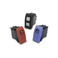
Switch Hardware ACTUATOR CONTURA III
Manufacturer
Carling Technologies
Type
Contura Rocker Switch Actuatorr
Series
Vr
Specifications of VVCMC00-000
Color
Red
Illumination
Not Illuminated
Mounting Style
Snap On
Lead Free Status / RoHS Status
Lead free / RoHS Compliant
For Use With
V Series


NOTES
Consult factory to verify horsepower rating for your particular circuit choice.
1
2
3
4
2 CIRCUIT
Terminal Connections as viewed
from bottom of switch:
8 terminal 10 terminal
8 - - 7
1 - - 4
2 - - 5
3 - - 6
Position:
SP
1
4
6
7
8
9
SPECIAL CIRCUITS
H*
G*
S
M*
R
E*
*Jumper between terminals 2 & 5 for circuits H, G, & M are specified in selection 4.
External jumper between terminals 2 & 4 for circuit E are provided by customer. Circuit E
may be used for SP OFF-ON-ON circuit. Circuits H, M & E not available with ratings 5 - 9.
3 RATING
1
4
5
8* 10A 250VAC, 15A 125VAC, 1/2 HP 125-250VAC, 12(2)A 250 VAC µ T85
9* 10A 250VAC, 15A 125VAC, 1/2 HP 125-250 VAC, 12(6)A 250 VAC T85
B 15A 24V
C 20A 18V
D 20A 12V
* Ratings 8 & 9 are UL, CSA, VDE, DEMKO, SEMKO, NEMKO, FIMKO & BEAB certified,
require terminations A or B for double pole circuits, & are not available with illumination cir-
cuits 4, 8, D, J, N, & T or with wire lead or solder lug terminations. Circuits 1, 4, A & D are
not available with rating 8. Rating 9 is only available with circuits 1, 4, A & D. Ratings 8 & 9
must specify lamp code 2 (250VAC neon).
Lamp #1 above terminals 1 & 4 end of switch.; Lamp #2 above terminals 3 & 6 end of switch.
Positive (+) and negative (-) symbols apply to LED lamps only
Sealed Unsealed Lamps when Illuminated
S
C
H
Selections for Double Pole Switches Only:
M
Lock above terminals 1 & 4 end of switch.
W
8 term
1
A
J
3
C
5
E
Note: Codes J & K for circuits H, G & M. Ratings 8 & 9 require terminations A or B only.
5 ILLUMINATION & SWITCH SEALING
6 LOCK
1 SERIES
V
4 TERMINATION/BASE STYLE
Custom colors are available. Consult factory.
White imprinting is standard on black actuators; Black imprinting is standard on white, red
and gray actuators; Custom colors are available, consult factory.
Only available with 3 position circuits. Center OFF and special circuits only available with
center position lock function.
Additional ratings available. See page 57.
.4VA @ 28VDC Resistive
10A 250VAC 1/2 HP, 15A 125VAC 1/2 HP, No Listings
10A 250VAC 1/2 HP, 15A 125VAC 1/2 HP, UL Recognized, CSA Certified
1
Series
V
DP
A
D
J
K
L
N
Carling
Technologies
10 term
2
B
K
4
D
6
F
0
3
Z
R
lock
10 - - 9
(2 & 3, 5 & 6)
(2 & 3, 5 & 6)
8 - - 7
1 - - 4
2 - - 5
3 - - 6
2 & 3, 5 & 6
2 & 3, 5 & 6
2 & 3, 5 & 6
2
Circuit
2 & 3
5 & 6
(ON)
OFF
ON
ON
ON
ON
1
1 D A S
Termination
.250 TAB (QC) no barriers
.250 TAB (QC) with barriers
.250 TAB (QC) no barriers
Solder Lug no barriers
Solder Lug
Wire Leads no barriers
Wire Leads
None
# 2
# 2
# 2
™
3
Rating
Connected Terminals
Actuator Lens position
Up
Independent
Up
2 & 3, 5 & 4
NONE
NONE
NONE
( ) - momentary
SP - single pole - uses terminals 1, 2 & 3.
DP - double pole uses terminals 1, 2, 3, 4, 5 & 6.
Terminals 7, 8, 9 & 10 for lamp circuit only.
2 & 3
2 & 3
2 & 3
2 & 3
5 & 3
OFF
OFF
OFF
2
4
Termination
5
Illumination
1 & 2, 4 & 5
Jumper
No
No
Yes T2 to 5
No
No
No
No
5 & 4
1 & 2
1 & 2
5 & 1
Lamp wired to
Terminals
3+
8+
3+
(ON)
(ON)
OFF
OFF
OFF
ON
ON
ON
3
W 0 B
6
Lock
V-Series Contura II & III Locking Sealed Rocker Switches
7-
7-
6-
www.carlingtech.com
7
Lamp
8
Bracket
45
7 LAMP
Lamp above terminals 3 & 6 end of switch.
No lamp
Neon
Incandescent 4 3V
LED *
2VDC
6VDC
12VDC
24VDC
* Consult factory for “daylight bright” LED options. Typical current draw for LED is 20ma.
8 FLUSH BRACKET COLOR
No Seal
One Seal
9 HARD SURFACE ACTUATOR
Contura II
Contura III
10 LENS
Lens color for LEDs must be clear, white, or match color of LED.
Green or blue lenses are not recommended with Neon lamps.
Z - No Lens
Clear
3
11 ACTUATOR LOCK FUNCTION AND COLOR
Lock Color
Match Actuator
Black
White
Red
Safety Orange
12 ACTUATOR LENS OR BODY LEGEND
13 LEGEND ORIENTATION
0
1
2
3
4
00 - No Legend
21
25 O
For additional legend options & codes, see page 69 of this catalog
AZC45-1
OFF
-
F
F
No legend
Orientation 1
Orientation 2
Orientation 3
Orientation 4
9
Actuator
A Z E
22
26
AZC45-2
0
1 125VAC 2 250VAC
Red
A
B
C
D
Black
B
C
Black
A
C
White
8
45
ON
O
N
Up
A
B
C
D
E
(used with codes 21-28 in selection 12)
10
Lens
23
27 O
Gray
B
D
Down
H
J
K
L
M
5 6V
Amber
L
M
N
P
White
W
Y
Amber
D
O
3
1
, PANEL SEAL
11
Function
Red
G
E
1
24
28 I
Actuator orientation above terminals:
ORIENTATION 4
6 12V
superbright superbright
Green
F
G
H
J
Gray
G
H
Green
J
Up & Down
R
S
T
V
W
I
White
H
F
12
Legend
2
00
1
7 18V
Red
R
S
T
V
Red
P
ORIENTATION 3
ACTUATOR/LENS IN PANEL
Center
1
2
3
4
5
ORIENTATION 1
ORIENTATION OF
-
3
8 24V
Blue
V
13
Legend
Orientation
0
ORIENTATION 2
3,6
1,4
49
Related parts for VVCMC00-000
Image
Part Number
Description
Manufacturer
Datasheet
Request
R

Part Number:
Description:
Toggle Switches CARLING TECHNOLOGIES
Manufacturer:
Carling Technologies
Datasheet:
Part Number:
Description:
CARLING POWER SWITCH LIGHTED 10 AMP 250 VOLT AC
Manufacturer:
Carling Technologies
Part Number:
Description:
CARLING SWITCH
Manufacturer:
Carling Technologies

Part Number:
Description:
SWITCH PB SPST OFF-MOM SCRW TERM
Manufacturer:
Carling Technologies
Datasheet:
Part Number:
Description:
SWITCH
Manufacturer:
Carling Technologies
Datasheet:

Part Number:
Description:
INDUCTOR PLATE FOR THERMAL BRKR
Manufacturer:
Carling Technologies

Part Number:
Description:
CIRCUIT BREAKER ROCKER 9A SP BK
Manufacturer:
Carling Technologies
Datasheet:

Part Number:
Description:
CIRCUIT BREAKER MAGNETIC 20A
Manufacturer:
Carling Technologies
Datasheet:
Part Number:
Description:
LIGHT INDICATOR GRN 12VDC PNLMNT
Manufacturer:
Carling Technologies
Part Number:
Description:
CONTURA ILL INDICATOR 12V RED
Manufacturer:
Carling Technologies
Part Number:
Description:
Current Regulator Diodes CURRENT REGULATOR DIODES 3.6mA
Manufacturer:
Carling Technologies
Part Number:
Description:
Rocker Switches
Manufacturer:
Carling Technologies
Datasheet: