S42-RO NKK Switches, S42-RO Datasheet - Page 9
S42-RO
Manufacturer Part Number
S42-RO
Description
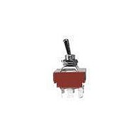
Toggle Switches 4PDT ON-NONE-ON
Manufacturer
NKK Switches
Series
Sr
Datasheet
1.S301.pdf
(11 pages)
Specifications of S42-RO
Contact Form
4PDT
Contact Current Rating
25 Amps at 125 Volts
Mounting Style
Panel
Terminal Seal
Resin
Contact Plating
Copper with Silver
Actuator
Bat
Switch Function
ON - NONE - ON
Termination Style
Solder Lug
Pole Throw Configuration
4PDT
Switch Configuration
ON None ON
Actuator Style
Bat Lever
Current Rating (max)
25A
Ac Voltage Rating (max)
250VVAC
Dc Voltage Rating (max)
30VVDC
Contact Material
Silver Alloy/Copper
Mechanical Life
50000
Product Height (mm)
56.6mm
Product Depth (mm)
36.5mm
Operating Temperature Min Deg. C
-10C
Product Length (mm)
34.2mm
Operating Temperature Max Deg. C
70C
Contact Rating
25 Amps at 125 Volts
Lead Free Status / RoHS Status
Lead free / RoHS Compliant
Other names
633-S42 S-42 S42


A
Series S
A110
General Specs. page for approval marks
General Specs. page for approval marks
*See Supplement section for UL detail &
*See Supplement section for UL detail &
Notes: Standard Hardware: AT503M Face Hex Nut, AT506M Locking Ring, AT508 Lockwasher, AT527M Backup Hex Nut. See Accessories & Hardware section.
Optional Splashproof Boot Assemblies: AT401 & AT4181 boots plus hex nut & o-ring. See Accessories & Hardware section.
Notes: Standard Hardware: AT503M Face Hex Nut, AT506M Locking Ring, AT508 Lockwasher, AT527M Backup Hex Nut. See Accessories & Hardware section.
Optional Splashproof Boot Assemblies: AT401 & AT4181 boots plus hex nut & o-ring. See Accessories & Hardware section.
Throw &
Schematics:
Model
Throw &
Schematics:
Model
S41F
S42F
S43F
S31F
S32F
S33F
S32F
S42F
R
R
4PST
*Approvals
*Approvals
1
3PST
C
C
US
US
1
3
Keyway
Keyway
4
(30.0)
Pole &
Throw
Pole &
Throw
1.181
4PDT
4PDT
3PST
3PDT
3PDT
3
4PST
(36.5)
1.437
4
6
ON 1-3 4-6 7-9 10-12
ON 2-3 5-6 8-9 11-12
ON 2-3 5-6 8-9 11-12
7
ON
ON
ON
THREE POLE WITH QUICK CONNECT
FOUR POLE WITH QUICK CONNECT
6
.240
(6.1) Dia
Keyway
25°
7
Down
1-3 4-6 7-9
2-3 5-6 8-9
2-3 5-6 8-9
.236
(6.0) Dia
Toggle Position/Connected Terminals
25°
Keyway
Down
9
10
Toggle Position/Connected Terminals
(17.5)
.689
M12 P1
9
www.nkk.com
(17.5)
.689
M12 P1
INTERNAL
CONNECTION
(12.0)
.472
12
Medium/High Capacity Standard Size Toggles
Center
NONE
NONE
OFF
INTERNAL
CONNECTION
(12.0)
.472
NONE
NONE
Center
OFF
OFF
ON
ON
(33.3)
3PDT
1.311
4PDT
OFF
(33.1)
1.303
ON 2-1 5-4 8-7 11-10
ON 2-1 5-4 8-7 11-10
2-1 5-4 8-7
2-1 5-4 8-7
3
3
(11.0)
.433
Up
(7.9)
.311
S31F does not have terminals 2, 5, & 8
(11.8)
.465
S41F does not have terminals 2, 5, 8, & 11
2
(7.9)
.311
.060
1
(1.5) Dia Typ
2
.295
(7.5) Typ
(6.35) Typ
.250
(0.8) Typ
.031
—
1
Up
.060
(1.5) Dia Typ
.295
(6.35) Typ
(7.5) Typ
.250
6
(0.8) Typ
.031
6
5
5
125V
25A
25A
25A
AC
4
(COM)
9
8
7
—
(COM)
4
12
11
10
9
9
Resistive
Electrical Capacity
250V
125V
25A
25A
25A
9A
9A
9A
9
AC
8
7
AC
8
5
6
4
7
8
Electrical Capacity
Resistive
7
12
250V
9A
9A
9A
2
AC
3
1
6
5
4
20A
20A
20A
11
30V
DC
(33.8)
1.331
Note: Terminal numbers
20A
20A
20A
30V
2
3
1
10
DC
Inductive
(34.2)
1.346
AC 125V
Note: Terminal
PF 0.6
Panel Thickness:
.181” (4.6mm)
10A
10A
10A
Inductive
AC 125V
are on the switch
PF 0.6
Panel Thickness:
10A
10A
10A
.181” (4.6mm)
Maximum
Maximum
numbers are
on the switch
(3.0) Dia
.118
(12.5) Dia
.492
of Throw
of Throw
.354
(3.0) Dia
.118
(9.0)
Angle
Angle
25°
25°
30°
α =
25°
25°
30°
α =
(12.5) Dia
.492
.354
(9.0)
Related parts for S42-RO
Image
Part Number
Description
Manufacturer
Datasheet
Request
R

Part Number:
Description:
SWITCH TOGGLE 4PDT 25A SLDR 5PCS
Manufacturer:
NKK Switches
Datasheet:

Part Number:
Description:
Rocker Switches & Paddle Switches High In-rush Rated Rocker Switch
Manufacturer:
NKK Switches
Datasheet:
Part Number:
Description:
Rocker Switches & Paddle Switches High In-rush Rated Rocker Switch
Manufacturer:
NKK Switches
Datasheet:
Part Number:
Description:
Rocker Switches & Paddle Switches High In-rush Rated Rocker Switch
Manufacturer:
NKK Switches
Datasheet:
Part Number:
Description:
Rocker Switches & Paddle Switches High In-rush Rated Rocker Switch
Manufacturer:
NKK Switches
Datasheet:

Part Number:
Description:
Pushbutton Switches SPST ON(OFF) 15/32'
Manufacturer:
NKK Switches
Datasheet:

Part Number:
Description:
Pushbutton Switches SPST OFF(ON) 15/32'
Manufacturer:
NKK Switches
Datasheet:

Part Number:
Description:
Pushbutton Switches ON(OFF) NORM CLSD 3A RED PLNGR LUG 15/32
Manufacturer:
NKK Switches
Datasheet:

Part Number:
Description:
Pushbutton Switches SPDT ON-(ON)
Manufacturer:
NKK Switches
Datasheet:

Part Number:
Description:
Pushbutton Switches ON-(ON) RND BUSH MNT RED LED RED/RED CAP
Manufacturer:
NKK Switches
Datasheet:
Part Number:
Description:
Pushbutton Switches SPST ON-(OFF) STRT
Manufacturer:
NKK Switches
Datasheet:
Part Number:
Description:
Pushbutton Switches OFF(ON) NORM OPEN 3A RED CAP LUG 15/32
Manufacturer:
NKK Switches
Datasheet:
Part Number:
Description:
Pushbutton Switches ILLUM PUSHBUTTON SPDT
Manufacturer:
NKK Switches
Datasheet:
Part Number:
Description:
Pushbutton Switches OFF(ON) NORM OPEN 3A BLK CAP LUG 15/32
Manufacturer:
NKK Switches
Datasheet:
Part Number:
Description:
Pushbutton Switches SPST NO Metric Thrd Blk Plunge w/Blu Cap
Manufacturer:
NKK Switches
Datasheet: