S33-RO NKK Switches, S33-RO Datasheet
S33-RO
Specifications of S33-RO


Related parts for S33-RO


S33-RO Summary of contents
Page 1
... DC 2,000V AC minimum for 1 minute minimum 50,000 operations minimum 6,000 operations minimum for S331F; 15,000 operations minimum for all other S331s; 25,000 operations minimum for all others Shown on following tables PBT for flatted lever; brass with chrome plating for all others ...
Page 2
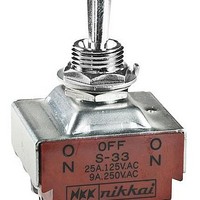
... INTERNAL CONNECTION DPDT (2.4) Dia Typ .094 6 3 (4.8) Typ .189 (5.7) .224 (25.1) S331 does not have .988 terminals 2 & 5 www.nkk.com Series S * Electrical Capacity Resistive Inductive 125V 250V 30V PF 0.6 15A 6A 20A 10A 15A 6A 20A 10A ...
Page 3
... Dia Typ .094 6 3 (4.8) Typ (33.2) 1.307 .189 (19.0) .748 Maximum S331R does not have Panel Thickness: terminals 2 & 5 .220” (5.6mm) α = Angle of Throw 25° 25° 30° 25° 25° (12.5) Dia .492 (9.0) .354 (3.0) Dia ...
Page 4
... OFF (ON) 2-1 5-4 2 (COM) DPDT INTERNAL CONNECTION M3 (6.6) .260 (6.6) .260 (1.0) Typ (26.0) .039 1.024 S331T does not have terminals 2 & 5 www.nkk.com Series S Electrical Capacity Resistive Inductive 125V 250V 30V PF 0.6 6A 20A 10A 6A 20A 10A 6A 20A 10A 6A 20A 8A 6A 20A ...
Page 5
... M12 P1 α (6.1) Dia .240 (11.7) .461 (17.5) (12.0) (30.3) .689 .472 1.193 S331F does not have terminals 2 & 5 www.nkk.com Electrical Capacity Resistive Inductive 125V 125V 250V 30V PF 0.6 15A 6A 20A 10A Note: Terminal numbers are actually on the switch (1 ...
Page 6
... Medium/High Capacity Standard Size Toggles GENERAL SPECIFICATIONS FOR S31 ~ S49 Electrical Capacity (Resistive & Inductive Load) Power Level: Shown in the following tables Other Ratings Contact Resistance: 10 milliohms maximum Insulation Resistance: 1,000 megohms minimum @ 500V DC Dielectric Strength: 2,000V AC minimum for 1 minute minimum ...
Page 7
... A *See Supplement section for UL detail & General Specs. page for approval marks *Approvals Pole & Model Throw S31 3PST S32 3PDT S33 3PDT S35 3PDT S38 3PDT S39 3PDT Throw & 3PST Schematics Notes: Standard Hardware: AT503M Face Hex Nut, AT506M Locking Ring, AT508 Lockwasher, AT527M Backup Hex Nut. See Accessories & Hardware section. ...
Page 8
... Model Throw S31T 3PST ON S32T 3PDT ON S33T 3PDT ON 3PST Throw & Schematics Notes: Standard Hardware: AT503M Face Hex Nut, AT506M Locking Ring, AT508 Lockwasher, AT527M Backup Hex Nut. See Accessories & Hardware section. Optional Splashproof Boot Assemblies: AT401 & AT4181 boots plus hex nut & o-ring. See Accessories & Hardware section. ...
Page 9
... Model Throw S31F 3PST S32F 3PDT S33F 3PDT Throw & 3PST Schematics Notes: Standard Hardware: AT503M Face Hex Nut, AT506M Locking Ring, AT508 Lockwasher, AT527M Backup Hex Nut. See Accessories & Hardware section. Optional Splashproof Boot Assemblies: AT401 & AT4181 boots plus hex nut & o-ring. See Accessories & Hardware section. ...
Page 10
... Medium/High Capacity Standard Size Toggles GENERAL SPECIFICATIONS FOR S421 ~ S429 Electrical Capacity (Resistive & Inductive Load) Power Level: Other Ratings Contact Resistance: Insulation Resistance: Dielectric Strength: Mechanical Life: Electrical Life: Angle of Throw (α): Materials & Finishes Toggle: Bushing: Case: Case Cover: ...
Page 11
... Notes: Standard Hardware: AT503M Face Hex Nut, AT506M Locking Ring, AT508 Lockwasher, AT527M Backup Hex Nut. See Accessories & Hardware section. Optional Splashproof Boot Assemblies: AT401 & AT4181 boots plus hex nut & o-ring. See Accessories & Hardware section. Keyway (19.0) .748 S423T A112 Medium/High Capacity Standard Size Toggles DOUBLE POLE WITH SOLDER LUG Toggle Position/Connected Terminals ( ) = Momentary Down Center Up ...