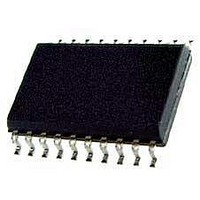
Si8518-C-IS Silicon Laboratories Inc, Si8518-C-IS Datasheet - Page 14

Si8518-C-IS
Manufacturer Part Number
Si8518-C-IS
Description
Board Mount Current Sensors 10A DUAL OUTPUT 5kV W/FAULT OUTPUT
Manufacturer
Silicon Laboratories Inc
Type
AC Current Sensorr
Series
-r
Datasheet
1.SI8503-C-IS.pdf
(36 pages)
Specifications of Si8518-C-IS
Current Rating
10 A
Supply Voltage
2.7 V to 5.5 V
Frequency Range
50 KHz to 1 MHz
Operating Temperature
- 40 C to + 125 C
Accuracy
5 %
Current - Sensing
10A
Sensitivity
196mV/A
Current - Supply
4mA
Sensor Type
Closed Loop
Voltage - Supply
2.7 V ~ 5.5 V
Output
Configurable
Frequency
50kHz ~ 1MHz
Response Time
-
Polarization
Unidirectional
Package / Case
20-SOIC (0.295", 7.50mm Width)
Lead Free Status / RoHS Status
Lead free / RoHS Compliant
Si85xx
3.3. Device Configuration
Configuring the Si85xx involves the following steps:
1. Selecting an output mode
2. Configuring integrator reset timing
3. Setting integrator reset time t
3.3.1. Device Selection
The Si85xx family offers three output modes: Single
output (Si850x), and 2 and 4-Wire Ping Pong (Si851x).
The Si851x products can be configured to operate in all
three of these output modes.
The Si850x products operate ONLY in Single output
mode. Most half-wave and single-phase applications
require only Single output mode and will typically use
the Si850x.
In Single output mode, output current always appears
on the OUT pin (Si850x) or the OUT1 pin (Si851x). A
single integrator reset signal is typically sufficient when
operating in this mode.
Ping-Pong mode routes the current waveform to two
different output pins on alternate measurement cycles.
It is useful in full-wave and push-pull topologies where
external circuitry can be used to monitor and/or control
transformer flux balance. (Section "3. Application
Information" on page 13 shows design examples using
both output modes in various power topologies.)
2-wire Ping-Pong mode is useful mainly in non-
overlapping two-phase buck converters but may also be
used in full-bridge applications. In this output mode,
reset inputs R1 and R2 are used, and input R3 is
grounded. Measured current appears on OUT1 when
R1 is high and on OUT2 when R2 is high as shown in
the full-bridge timing example of Figures 10 and 11.
14
Figure 10. Two-Phase Buck Timing Example A
Si85xx State
OUT1
OUT2
R2
R1
MEASURE
RESET
tR
TIME
R
MEASURE RESET
tR
Preliminary Rev. 0.21
4-Wire Ping-Pong mode is recommended for full-bridge
applications over 2-wire because it uses all four inputs,
making the reset function tolerant to single-point signal
failures. In 4-Wire Ping-Pong mode, current appears on
OUT2 when R1 is high and R2 is low, and appears on
OUT1 when R3 is high and R4 is low as shown in the
full-bridge timing example of Figure 12. Table 11 shows
the states of the Mode and R4 inputs that select each
output, and the resulting reset logic functions and truth
tables.
Si85xx State
Figure 11. Full-Bridge Timing Example B
Figure 12. Full-Bridge Timing Example C
OUT1
OUT2
OUT1
OUT2
R1
R2
R3
R4
R2
R1
MEASURE
MEASURE
RESET
RESET
tR
tR
TIME
MEASURE RESET
MEASURE
tR
RESET
tR


