E2EM-X4X1-2M Omron, E2EM-X4X1-2M Datasheet - Page 3
E2EM-X4X1-2M
Manufacturer Part Number
E2EM-X4X1-2M
Description
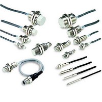
Proximity Sensors M12 shielded 4mm NO Xtnded rng inductive
Manufacturer
Omron
Type
Inductive Proximity Sensorr
Series
E2EMr
Datasheet
1.E2EM-X8X1-2M.pdf
(9 pages)
Specifications of E2EM-X4X1-2M
Maximum Operating Temperature
+ 70 C
Supply Voltage
24 V
Operating Supply Voltage
10 V to 30 V
Mounting Style
Panel
Minimum Operating Temperature
- 25 C
Maximum Output Current
100 mA
Barrel Size
M12
Features
Reduces problems such as collision of work pieces
Sensing Distance
4 mm
Lead Free Status / RoHS Status
Lead free / RoHS Compliant


E2EM-X@C@ DC 3-Wire Models
*1. The response frequency is an average value.
*2. When using an M8 Model at an ambient temperature between 70 and 85°C, supply 10 to 30 VDC to the Sensor and make sure that the Sensor has a control output
Item
Sensing distance
Set distance
Differential travel
Detectable object
Standard sensing object
Response frequency *1
Power supply voltage
(operating voltage range) *2
Current consumption
Control
output
Indicators
Operation mode (with sens-
ing object approaching)
Protection circuits
Ambient temperature range
*1
Ambient humidity range
Temperature influence
Voltage influence
Insulation resistance
Dielectric strength
Vibration resistance
Shock resistance
Degree of protection
Connection method
Weight
(packed
state)
Materials
Accessories
Measurement conditions are as follows: standard sensing object, a distance of twice the standard sensing object, and a set distance of half the sensing distance.
of 100 mA maximum.
Load current *2
Residual
voltage
Pre-wired Models Approx. 65 g
Connector Mod-
els
Case
Sensing surface
Clamping nuts
Toothed washer
Shielded
Model
Size
2 mm ±10%
0 to 1.6 mm
10% max. of sensing distance
Ferrous metal (The sensing distance decreases with non-ferrous metal. Refer to Engineering Data on page 4.)
Iron, 8 × 8 × 1 mm
1.5 kHz
12 to 24 VDC (10 to 40 VDC), ripple (p-p): 10% max.
13 mA max.
200 mA max.
2 V max. (Load current: 200 mA, Cable length: 2 m)
Operation indicator (yellow)
C1 Models: NO
C2 Models: NC
Reverse polarity protection, Load short-circuit protection, Surge suppressor
Operating/Storage: −40 to 85°C (with no icing or condensation)
Operating/Storage: 35% to 95% (with no condensation)
±15% max. of sensing distance at 23°C in the temperature range of −40 to 85°C
±10% max. of sensing distance at 23°C in the temperature range of −25 to 70°C
±1% max. of sensing distance at rated voltage in the rated voltage ±15% range
50 MΩ min. (at 500 VDC) between current-carrying parts and case
1,000 VAC, 50/60 Hz for 1 minute between current-carrying parts and case
Destruction: 10 to 55 Hz, 1.5-mm double amplitude for 2 hours each in X, Y, and Z directions
Destruction: 500 m/s
times each in X, Y, and Z
directions
Pre-wired Models: IEC 60529 IP67, in-house standards: oil-resistant
Connector Models: IEC 60529 IP67
Pre-wired Models (Standard cable length: 2 m)
Connector Models
Approx. 15 g
Stainless steel (SUS303)
PBT
Nickel-plated brass
Zinc-plated iron
Instruction manual
E2EM-X2C@(-M1)
Shielded
M8
Refer to the timing charts under I/O Circuit Diagrams on page 5 for details.
2
10
4 mm ±10%
0 to 3.2 mm
Iron, 12 × 12 × 1 mm
0.5 kHz
Destruction: 1,000 m/s
Approx. 75 g
Approx. 25 g
Nickel-plated brass
E2EM-X4C@(-M1)
Shielded
M12
2
10 times each in X, Y, and Z directions
8 mm ±10%
0 to 6.4 mm
Iron, 18 × 18 × 1 mm
0.3 kHz
Approx. 150 g
Approx. 40 g
E2EM-X8C@(-M1)
Shielded
M18
15 mm ±10%
0 to 12 mm
Iron, 30 × 30 × 1 mm
0.1 kHz
Operating: −25 to 70°C
Storage: −40 to 85°C (with
no icing or condensation)
±15% max. of sensing dis-
tance at 23°C in the tem-
perature range of −25 to
70°C
Approx. 195 g
Approx. 90 g
E2EM-X15C@(-M1)
Shielded
M30
E2EM
3
Related parts for E2EM-X4X1-2M
Image
Part Number
Description
Manufacturer
Datasheet
Request
R

Part Number:
Description:
Proximity Sensors M18 shielded 8mm NO Xtnded rng inductive
Manufacturer:
Omron
Datasheet:
Part Number:
Description:
Proximity Sensors M30 unshlded 30mm NO Xtnded rng inductive
Manufacturer:
Omron
Datasheet:
Part Number:
Description:
Proximity Sensors 2-WIRE 15mm M30 N/O SHIELDED 2M WIRE
Manufacturer:
Omron
Datasheet:
Part Number:
Description:
Inductive Proximity Sensor
Manufacturer:
Omron
Datasheet:
Part Number:
Description:
E2EM-C30X15 W/ M12Pigtail Conn
Manufacturer:
Omron
Part Number:
Description:
Extnd M30 Shd PNP-NO 15mm M12
Manufacturer:
Omron
Datasheet:
Part Number:
Description:
EXTND M8 SHD PNP-NO 2MM M12
Manufacturer:
Omron
Datasheet:
Part Number:
Description:
Extnd M12 Shd PNP-NO 4mm M12
Manufacturer:
Omron
Datasheet:

Part Number:
Description:
Proximity Sensors M8 NPN Out 2mm 3WIRE Xtnded rng inductive
Manufacturer:
Omron
Datasheet:
Part Number:
Description:
Proximity Sensors Extnd m30 Shd NPN-NO 15mm M12
Manufacturer:
Omron
Datasheet:

Part Number:
Description:
PROXIMITY SENSOR
Manufacturer:
Omron
Datasheet:
