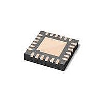
MAX6581TG9C+ Maxim Integrated Products, MAX6581TG9C+ Datasheet - Page 22

MAX6581TG9C+
Manufacturer Part Number
MAX6581TG9C+
Description
Board Mount Temperature Sensors 1 C ACCUR 8-CH TEMP SENSR
Manufacturer
Maxim Integrated Products
Datasheet
1.MAX6581ATG9A.pdf
(24 pages)
Specifications of MAX6581TG9C+
Full Temp Accuracy
+/- 1 C
Package / Case
TQFN-24
Digital Output - Bus Interface
I2C
Digital Output - Number Of Bits
11 bit
Supply Voltage (max)
3.6 V
Supply Voltage (min)
3 V
Description/function
Multichannel Temperature Sensor
Maximum Operating Temperature
+ 125 C
Minimum Operating Temperature
- 40 C
Supply Current
4 uA
Lead Free Status / RoHS Status
Lead free / RoHS Compliant
±1°C Accurate 8-Channel Temperature Sensor
Figure 5. Recommended DXP_–DXN_ PCB Traces. The two
outer guard traces are recommended if high-voltage traces
are near the DXN_ and DXP_ traces.
Follow the guidelines below to reduce the measurement
error when measuring remote temperature:
1) Place the MAX6581 as close as possible to the
2) Do not route the DXP_–DXN_ lines next to the deflec-
3) Route the DXP_ and DXN_ traces in parallel and in
22
5–10 mils
5–10 mils
remote diode. In noisy environments, such as a com-
puter motherboard, this distance is typically 4in to
8in. This length can be increased if the worst-noise
sources are avoided. Noise sources include displays,
clock generators, memory buses, and PCI buses.
tion coils of a CRT. Also, do not route the traces
across fast digital signals, which can easily introduce
+30NC error, even with good filtering.
close proximity to each other. Each parallel pair of
traces should go to a remote diode. Route these
_____________________________________________________________________________________
DXN_
DXP_
GND
GND
PCB Layout
5–10 mils
MINIMUM
5–10 mils
4) Route through as few vias and crossunders as possi-
5) Use wide traces when possible (5-mil to 10-mil traces
6) When the power supply is noisy, add a resistor (up to
Use a twisted-pair cable to connect the remote sensor
for remote-sensor distances longer than 8in or in very
noisy environments. Twisted-pair cable lengths can be
between 6ft and 12ft before noise introduces excessive
errors. For longer distances, the best solution is a shield-
ed twisted pair such as those used for audio micro-
phones. For example, Belden #8451 works well for dis-
tances up to 100ft in a noisy environment. At the device,
connect the twisted-pair cables to DXP_ and DXN_ and
the shielded cable to GND. Leave the shielded cable
unconnected at the remote sensor. For very long cable
runs, the cable’s parasitic capacitance often provides
noise filtering; therefore the 100pF capacitor can often
be removed or reduced in value. Cable resistance also
affects remote-sensor accuracy. For every 1I of series
resistance, the error is approximately +0.5NC.
traces away from any higher voltage traces, such as
+12V
must be dealt with carefully since a 20MI leakage
path from DXP_ to ground causes approximately
+1NC error. If high-voltage traces are unavoidable,
connect guard traces to GND on either side of the
DXP_–DXN_ traces (Figure 5).
ble to minimize copper/solder thermocouple effects.
are typical). Be aware of the effect of trace resistance
on temperature readings when using long, narrow
traces.
47I) in series with V
DC
. Leakage currents from PCB contamination
Twisted-Pair and Shielded Cables
CC
.


