UCE-12/4.2-D48N-C Murata Power Solutions Inc, UCE-12/4.2-D48N-C Datasheet - Page 4
UCE-12/4.2-D48N-C
Manufacturer Part Number
UCE-12/4.2-D48N-C
Description
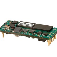
DC/DC Converters & Regulators 48Vin 12Vout 4.2A 50.4W Neg polarity
Manufacturer
Murata Power Solutions Inc
Specifications of UCE-12/4.2-D48N-C
Output Power
50 W
Input Voltage Range
36 V to 75 V
Input Voltage (nominal)
48 V
Number Of Outputs
1
Output Voltage (channel 1)
12 V
Output Current (channel 1)
4.2 A
Isolation Voltage
2.25 KV
Package / Case Size
Eighth Brick
Output Voltage
12 V
Product
Isolated
Dc / Dc Converter O/p Type
Eighth-Brick
No. Of Outputs
1
Input Voltage
36V To 75V
Power Rating
50.4W
Output Current
4.2A
Approval Bodies
CAN / CSA / EN / IEC / UL
Rohs Compliant
Yes
Lead Free Status / RoHS Status
Lead free / RoHS Compliant


(1) All models are tested and specified with external 1||10 µF ceramic/tantalum output
capacitors and no external input capacitor. All capacitors are low ESR types. These
capacitors are necessary to accommodate our test equipment and may not be required
to achieve specified performance in your applications. All models are stable and regulate
within spec under no-load conditions.
General conditions for Specifications are +25 deg.C, V
load. Adequate airflow must be supplied for extended testing under power.
(2) Input Ripple Current is tested and specified over a 5 Hz to 20 MHz bandwidth. Input
filtering is C
(3) Note that Maximum Power Derating curves indicate an average current at nominal
input voltage. At higher temperatures and/or lower airflow, the DC/DC converter will
tolerate brief full current outputs if the total RMS current over time does not exceed
the Derating curve. All Derating curves are presented at sea level altitude. Be aware of
reduced power dissipation with increasing density altitude.
(4) Mean Time Before Failure is calculated using the Telcordia (Belcore) SR-332 Method 1,
Case 3, ground fixed conditions, Tpcboard=+25 deg.C, full output load, natural air
convection.
(5) The On/Off Control is normally controlled by a switch. But it may also be driven with
external logic or by applying appropriate external voltages which are referenced to Input
Common. The On/Off Control Input should use either an open collector or open drain
transistor.
(6) Short circuit shutdown begins when the output voltage degrades approximately 2%
from the selected setting.
UCE-1.5/20-D48
UCE-1.8/30-D48
UCE-3.3/15-D48
UCE-3.3/30-D48
UCE-12/4.2-D48
UCE-12/8.3-D48
PERFORMANCE SPECIFICATION NOTES
DYNAMIC CHARACTERISTICS
Model Family
in
= 33 µF, 100V tantalum, C
Dynamic Load
to ±1% of final
30-200 μSec
(50-75-50%
value, model
Response
load step)
dependent
bus
5-50, model
V
dependent
regulated
= 220 µF, 100V electrolytic, L
in
(Max.)
to V
Start-up Time
out
mSec
in
www.murata-ps.com
= nominal, V
Remote On/
5-50, model
Off to V
dependent
regulated
(Max.)
out
out
= nominal, full
bus
Frequency
Switching
400 ±40
480 ±50
380 ±40
200 ±10
= 12 µH.
KHz
480
(7) The outputs are not intended to sink appreciable reverse current. This may damage
the outputs.
(8) Output noise may be further reduced by adding an external filter. See I/O Filtering and
Noise Reduction.
(9) All models are fully operational and meet published specifications, including “cold
start” at –40ºC.
(10) Regulation specifications describe the deviation as the line input voltage or output
load current is varied from a nominal midpoint value to either extreme.
(11) Alternate pin length and/or other output voltages are available under special quantity
order.
(12) Output current limit is non-latching. When the overcurrent fault is removed, the
converter will immediately recover.
(13) Do not exceed maximum power specifications when adjusting the output trim.
(14) At zero output current, the output may contain low frequency components which
exceed the ripple specification. The output may be operated indefinitely with no load.
(15) If reverse polarity is accidentally applied to the input, a body diode will become
forward biased and will conduct considerable current. To ensure reverse input protection
with full output load, always connect an external input fuse in series with the +V
Use approximately twice the full input current rating with nominal input voltage.
ABSOLUTE MAXIMUM RATINGS
Input Voltage:
On/Off Control
Input Reverse Polarity Protection
Output Overvoltage Protection
Output Current *
Storage Temperature
Lead Temperature
Absolute maximums are stress ratings. Exposure of devices to any of these conditions
may adversely affect long-term reliability. Proper operation under conditions other
than those listed in the Performance/Functional Specifications Table is not implied nor
recommended.
Note: Not all model combinations are available.
Continuous:
Transient (100 mSec. Max.)
48 Volt input models
48 Volt input models
Technical enquiries email: sales@murata-ps.com, tel:
Isolated, High-Density, Eighth-Brick
100W DC/DC Converters
75 Volts
100 Volts
+15 Volts
5 Amps, 10 sec. max.
Magnetic feedback.
See specifications.
Current-limited. Devices can
withstand sustained short circuit
without damage.
–40 to +125°C.
+280°C, 10 seconds max.
UCE Series
MDC_UCE.A09 Page 4 of 10
+1 508 339 3000
in
input.
Related parts for UCE-12/4.2-D48N-C
Image
Part Number
Description
Manufacturer
Datasheet
Request
R

Part Number:
Description:
CONV DC/DC 50.4W 12V 4.2A
Manufacturer:
Murata Power Solutions Inc
Datasheet:

Part Number:
Description:
DC/DC Converters & Regulators 48Vin 12Vout 4.2A 50.4W W/Baseplate
Manufacturer:
Murata Power Solutions Inc
Datasheet:
Part Number:
Description:
DC/DC Converters & Regulators 48Vin 12Vout 4.2A 50.4W Pos polarity
Manufacturer:
Murata Power Solutions Inc
Datasheet:

Part Number:
Description:
CONV DC/DC 120W 12V 10A
Manufacturer:
Murata Power Solutions Inc
Datasheet:
Part Number:
Description:
CONV DC/DC 120W 12V 10A
Manufacturer:
Murata Power Solutions Inc
Datasheet:
Part Number:
Description:
CONV DC/DC 120W 12V 10A W/BASEPL
Manufacturer:
Murata Power Solutions Inc
Datasheet:
Part Number:
Description:
CONV DC/DC 120W 12V 10A W/BASEPL
Manufacturer:
Murata Power Solutions Inc
Datasheet:
Part Number:
Description:
CONV DC/DC 99.6W 12V 8.3A
Manufacturer:
Murata Power Solutions Inc
Datasheet:
Part Number:
Description:
DC/DC Converters & Regulators 48Vin 12Vout 8.3A 99.6W Neg polarity
Manufacturer:
Murata Power Solutions Inc
Datasheet:
Part Number:
Description:
DC/DC Converters & Regulators 48Vin 12Vout 8.3A 99.6W Pos polarity
Manufacturer:
Murata Power Solutions Inc
Datasheet:

Part Number:
Description:
Transformers 5Vin 5Vout 200mA 4000Vdc 1:1.33 turn
Manufacturer:
Murata Power Solutions Inc
Datasheet:

Part Number:
Description:
POWER SUPPLY
Manufacturer:
Murata Power Solutions Inc
Datasheet:

Part Number:
Description:
DPM LED MINI 2VDC 3.5DIG LP RED
Manufacturer:
Murata Power Solutions Inc
Datasheet:

Part Number:
Description:
CONV DC/DC 1W 5VIN 5VOUT SIP SGL
Manufacturer:
Murata Power Solutions Inc
Datasheet:

Part Number:
Description:
CONV DC/DC 1W 5VIN 3.3V SIP SGL
Manufacturer:
Murata Power Solutions Inc
Datasheet: