ULE-5/12-D24P-C Murata Power Solutions Inc, ULE-5/12-D24P-C Datasheet - Page 15
ULE-5/12-D24P-C
Manufacturer Part Number
ULE-5/12-D24P-C
Description
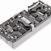
DC/DC Converters & Regulators 60W 24V to 5V 12A POSITVE POLARITY
Manufacturer
Murata Power Solutions Inc
Series
ULEr
Type
Step Downr
Specifications of ULE-5/12-D24P-C
Output Power
60 W
Input Voltage Range
18 V to 36 V
Input Voltage (nominal)
24 V
Number Of Outputs
1
Output Voltage (channel 1)
5 V
Output Current (channel 1)
12 A
Isolation Voltage
2.25 KV
Package / Case Size
Eighth Brick
Product
Isolated
Output Current
12A
Input Voltage
24V
Output Voltage
5V
Screening Level
Industrial
Product Length (mm)
58.4mm
Product Depth (mm)
22.9mm
Mounting Style
Through Hole
Pin Count
8
Package / Case
1/8-Brick
Lead Free Status / RoHS Status
Lead free / RoHS Compliant
Other names
ULE-5/12-D24P-C


tolerances and factory-adjusted output accuracy. V
Soldering Guidelines
Murata Power Solutions recommends the specifi cations below when installing these
converters. These specifi cations vary depending on the solder type. Exceeding these
specifi cations may cause damage to the product. Be cautious when there is high
atmospheric humidity. Your production environment may differ therefore please
thoroughly review these guidelines with your process engineers.
Reflow Solder Operations for surface-mount products (SMT)
For Sn/Ag/Cu based solders:
Preheat Temperature
Time over Liquidus
Maximum Peak Temperature
Cooling Rate
For Sn/Pb based solders:
Preheat Temperature
Time over Liquidus
Maximum Peak Temperature
Cooling Rate
Wave Solder Operations for through-hole mounted products (THMT)
For Sn/Ag/Cu based solders:
Maximum Preheat Temperature
Maximum Pot Temperature
Maximum Solder Dwell Time
For Sn/Pb based solders:
Maximum Preheat Temperature
Maximum Pot Temperature
Maximum Solder Dwell Time
Note: Resistor values are in kΩ. Adjustment accuracy is subject to resistor
R
R
R
R
T
T
T
T
UP
UP
UP
UP
(k ) =
(k ) =
(k ) =
(k ) =
13.3(V
20.4(V
49.6(V
62.9(V
Trim Up
V
V
V
V
O
O
O
O
O
O
O
O
– 3.3
– 12
– 15
– 1.226)
– 1.226)
– 5
– 1.226)
– 1.226)
Less than 1 ºC. per second
45 to 75 seconds
260 ºC.
Less than 3 ºC. per second
Less than 1 ºC. per second
60 to 75 seconds
235 ºC.
Less than 3 ºC. per second
115° C.
270° C.
7 seconds
105° C.
250° C.
6 seconds
Trim Equations
3.3 Volt Output
–10.2
–10.2
–10.2
–10.2
12 Volt Output
15 Volt Output
5 Volt Output
R
R
R
R
T
T
T
T
DOWN
DOWN
DOWN
DOWN
O
= desired output voltage.
(k ) =
(k ) =
(k ) =
(k ) =
Trim Down
3.3 – V
12 – V
15 – V
5 – V
16.31
25.01
60.45
76.56
www.murata-ps.com
O
O
O
O
–10.2
–10.2
–10.2
–10.2
through low value resistors. Nevertheless, if the sense function is not used for
remote regulation the user should connect the +Sense to +V
–V
tion, thereby overcoming moderate IR drops in pcb conductors or cabling.
The remote sense lines carry very little current and therefore require minimal
cross-sectional-area conductors. The sense lines are used by the feedback
control-loop to regulate the output. As such, they are not low impedance points
and must be treated with care in layouts and cabling. Sense lines on a pcb
should be run adjacent to dc signals, preferably ground. In cables and discrete
wiring applications, twisted pair or other techniques should be implemented.
at the DC/DC and the sense voltage at the DC/DC provided that:
the Sense pin. Therefore, excessive voltage differences between V
Sense in conjunction with trim adjustment of the output voltage can cause the
overvoltage protection circuitry to activate (see Performance Specifi cations
for overvoltage limits). Power derating is based on maximum output current
and voltage at the converter’s output pins. Use of trim and sense functions can
cause output voltages to increase thereby increasing output power beyond the
ULE’s specifi ed rating or cause output voltages to climb into the output over-
voltage region. Also, the use of Trim Up and Sense combined may not exceed
+10% of V
Remote Sense Note: The Sense and V
OUT
ULE series converters have a sense feature to provide point of use regula-
ULE series converters will compensate for drops between the output voltage
Output overvoltage protection is monitored at the output voltage pin, not
at the DC/DC converter pins.
OUT
[V
(V
–INPUT
ON/OFF
CONTROL
+INPUT
OUT
OUT
. Therefore, the designer must ensure:
(+) –V
at pins) x (I
Figure 9. Remote Sense Circuit Confi guration
OUT
(–)] –[Sense(+) –Sense (–)] ≤ 5% V
OUT
Isolated, High Density, Eighth-Brick
) ≤ rated output power
+OUTPUT
11 May 2011
–OUTPUT
1.25–20 Amp, DC/DC Converters
+SENSE
–SENSE
TRIM
OUT
Contact and PCB resistance
Contact and PCB resistance
lines are internally connected
Sense Current
losses due to IR drops
losses due to IR drops
MDC_ULE Series.E01 Page 15 of 26
Sense Return
email: sales@murata-ps.com
I
OUT
ULE Series
I
OUT
Return
OUT
OUT
and –Sense to
LOAD
OUT
and
Related parts for ULE-5/12-D24P-C
Image
Part Number
Description
Manufacturer
Datasheet
Request
R

Part Number:
Description:
DC/DC TH 12A 24-5V E-Brick
Manufacturer:
Murata Power Solutions Inc
Datasheet:
Part Number:
Description:
DC/DC SM 12A 24-5V E-Brick
Manufacturer:
Murata Power Solutions Inc
Part Number:
Description:
DC/DC TH 12A 48-5V E-Brick
Manufacturer:
Murata Power Solutions Inc
Part Number:
Description:
DC/DC SM 12A 48-5V E-Brick
Manufacturer:
Murata Power Solutions Inc
Part Number:
Description:
DC/DC TH 12A 48-5V E-Brick
Manufacturer:
Murata Power Solutions Inc
Part Number:
Description:
DC/DC SM 12A 48-5V E-Brick
Manufacturer:
Murata Power Solutions Inc

Part Number:
Description:
DC/DC SM 12A 24-5V E-Brick
Manufacturer:
Murata Power Solutions Inc
Part Number:
Description:
DC/DC Converters & Regulators 50W 12V to 5V 10A POSITVE POLARITY
Manufacturer:
Murata Power Solutions Inc
Datasheet:
Part Number:
Description:
DC/DC SM 10A 12-5V E-Brick
Manufacturer:
Murata Power Solutions Inc
Part Number:
Description:
DC/DC TH 10A 12-5V E-Brick
Manufacturer:
Murata Power Solutions Inc
Part Number:
Description:
DC/DC TH 20A 24-2.5V E-Brick
Manufacturer:
Murata Power Solutions Inc
Datasheet:

Part Number:
Description:
Transformers 5Vin 5Vout 200mA 4000Vdc 1:1.33 turn
Manufacturer:
Murata Power Solutions Inc
Datasheet:
Part Number:
Description:
POWER SUPPLY
Manufacturer:
Murata Power Solutions Inc
Datasheet:

Part Number:
Description:
DPM LED MINI 2VDC 3.5DIG LP RED
Manufacturer:
Murata Power Solutions Inc
Datasheet:

Part Number:
Description:
CONV DC/DC 1W 5VIN 5VOUT SIP SGL
Manufacturer:
Murata Power Solutions Inc
Datasheet: