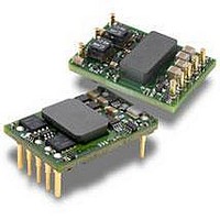
PKU4513PI Ericsson Power Modules, PKU4513PI Datasheet - Page 31

PKU4513PI
Manufacturer Part Number
PKU4513PI
Description
DC/DC Converters & Regulators 12Vdc 4.2A Isolated Input 36-75V 50W
Manufacturer
Ericsson Power Modules
Series
PKUr
Datasheet
1.PKU4513PI.pdf
(38 pages)
Specifications of PKU4513PI
Output Power
50 W
Input Voltage Range
36 V to 75 V
Number Of Outputs
1
Output Voltage (channel 1)
12 V
Output Current (channel 1)
4.2 A
Isolation Voltage
1.5 KV
Package / Case Size
Sixteenth Brick
Output Type
Isolated
Product
Isolated
Lead Free Status / RoHS Status
Lead free / RoHS Compliant
Available stocks
Company
Part Number
Manufacturer
Quantity
Price
Company:
Part Number:
PKU4513PI
Manufacturer:
ERICSSON
Quantity:
12 000
Operating information continued
Output Voltage Adjust (V
The DC/DC converters have an Output Voltage Adjust pin
(V
or below Output voltage initial setting.
When increasing the output voltage, the voltage at the output
pins (including any remote sense compensation ) must be
kept below the threshold of the over voltage protection, (OVP)
to prevent the converter from shutting down. At increased
output voltages the maximum power rating of the converter
remains the same, and the max output current must be
decreased correspondingly.
To increase the voltage the resistor should be connected
between the V
Output voltage adjust function is according to information
given under the Output section for the respective product.
To decrease the output voltage, the resistor should be
connected between the V
Parallel Operation
Two converters may be paralleled for redundancy if the total
power is equal or less than P
parallel the converters without using external current sharing
circuits.
See Design Note 006 for detailed information.
Remote Sense
The DC/DC converters have remote sense that can be used
to compensate for voltage drops between the output and the
point of load. The sense traces should be located close to the
PCB ground layer to reduce noise susceptibility. The remote
sense circuitry will compensate for up to 10% voltage drop
between output pins and the point of load.
If the remote sense is not needed +Sense should be
connected to +Out and -Sense should be connected to -Out.
Over Temperature Protection (OTP)
The converters are protected from thermal overload by an
internal over temperature shutdown circuit.
When T
Prepared (also subject responsible if other)
EJUNGYA
Approved
SEC/D (Julia You)
PKU 4000 Series
DC/DC converters, Input 36-75 V, Output 25 A/50 W
adj
). This pin can be used to adjust the output voltage above
ref
as defined in thermal consideration section
adj
pin and +Sense pin. The resistor value of the
adj
adj
)
pin and —Sense pin.
O
max. It is not recommended to
Checked
EQUENXU
PRODUCT SPECIFICATION
No.
3/1301-BMR 602 Uen
Date
2008-6-10
exceeds 135°C the converter will shut down. The DC/DC
converter will make continuous attempts to start up (non-
latching mode) and resume normal operation automatically
when the temperature has dropped >5°C below the
temperature threshold.
Over Voltage Protection (OVP)
The converters have output over voltage protection that will
shut down the converter in over voltage conditions. The
converter will make continuous attempts to start up (non-
latching mode, hiccup) and resume normal operation
automatically after removal of the over voltage condition.
Over Current Protection (OCP)
The converters include current limiting circuitry for protection
at continuous overload.
The output voltage will decrease towards zero for output
currents in excess of max output current (max I
output voltage decreases down to 0.5-0.6 V the converter
shuts down and will make continuous attempts to start up
(non-latching mode, hiccup). The converter will resume
normal operation after removal of the overload. The load
distribution should be designed for the maximum output short
circuit current specified.
Pre-bias Start-up
The product has a Pre-bias start up functionality and will not
sink current during start up if a pre-bias source is present at
the output terminals.
Typical Pre-bias source levels for no negative current:
Up to 0.5 V for PKU 4318L (1.2 V)
Up to 0.7 V for PKU 4318H (1.5 V)
Up to 1.0 V for PKU 4418G (1.8 V)
Up to 1.5 V for PKU 4319 (2.5 V)
Up to 2.0 V for PKU 4510 (3.3 V)
Up to 3.0 V for PKU 4511 (5 V)
Up to 6.0 V for PKU 4513 (12 V)
Up to 9.0 V for PKU 4515 (15 V)
Technical Specifi cation
EN/LZT 146 308 R4B July 2008
© Ericsson Power Modules AB
Rev
F
Reference
O
). If the
3 (6)
31


