BMR4500002/020 Ericsson Power Modules, BMR4500002/020 Datasheet - Page 19
BMR4500002/020
Manufacturer Part Number
BMR4500002/020
Description
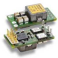
DC/DC Converters & Regulators 66W 4.5-14V OUT 20A 25.65x12.9x8.22 mm
Manufacturer
Ericsson Power Modules
Series
BMR 450r
Datasheet
1.BMR4500002020.pdf
(31 pages)
Specifications of BMR4500002/020
Output Power
110 W
Input Voltage Range
4.5 V to 14 V
Number Of Outputs
1
Output Voltage (channel 1)
0.6 V to 5.5 V
Output Current (channel 1)
20 A
Package / Case Size
25.65 mm x 12.9 mm x 8.2 mm
Output Voltage
0.6 V to 5.5 V
Product
Non-Isolated / POL
Lead Free Status / RoHS Status
Lead free / RoHS Compliant


when an appropriate input voltage is applied, or turn on/off can
be performed with PMBus commands. Please contact your
local Ericsson Power Modules representative for design
support of custom configurations or appropriate SW tools for
design and down-load of new configurations.
Input and Output Impedance
The impedance of both the input source and the load will
interact with the impedance of the product. It is important that
the input source has low characteristic impedance. The
products are designed for stable operation without external
capacitors connected to the input or output. The performance
in some applications can be enhanced by addition of external
capacitance as described under External Capacitors. If the
input voltage source contains significant inductance, the
addition of a 470 µF capacitor with low ESR at the input of the
product will ensure stable operation.
External Decoupling Capacitors
Input capacitors:
The recommended input capacitor has a minimum
capacitance of 470 µF and a low ESR. The ripple current
rating of the capacitor must be at least 4 A rms. For high-
performance/transient applications or wherever the input
source performance is degraded, additional low ESR ceramic
type capacitors at the input is recommended. The additional
input low ESR capacitance above the minimum level insures
an optimized performance.
Output capacitors:
The recommended output capacitor has a minimum
capacitance of 470 µF and a low ESR. When powering loads
with significant dynamic current requirements, the voltage
regulation at the point of load can be improved by addition of
decoupling capacitors at the load.
The most effective technique is to locate low ESR ceramic and
electrolytic capacitors as close to the load as possible, using
several capacitors in parallel to lower the effective ESR. The
ceramic capacitors will handle high-frequency dynamic load
changes while the electrolytic capacitors are used to handle
low frequency dynamic load changes. Ceramic capacitors will
also reduce high frequency noise at the load.
It is equally important to use low resistance and low
inductance PCB layouts and cabling.
External decoupling capacitors are a part of the control loop of
the product and may affect the stability margins. The ESR of
the capacitors is a very important parameter. Stable operation
is guaranteed for an ESR value of >5 mΩ and a total
capacitance in the range defined in the electrical specification.
For a total capacitance outside this range or with lower ESR a
re-configuration will be necessary for robust dynamic
operation and stability. Please contact your local Ericsson
Power Modules representative for design support of custom
configurations or appropriate SW tools for design and down-
load of new configurations.
E
Prepared (also subject responsible if other)
EAB/FJB/GMF EKAMAGN
Approved
EAB/FJB/GMF Torbjörn Holmberg
BMR 450 Digital PoL Regulators
Input 4.5-14 V, Output up to 20 A / 100 W
Checked
ETORHOL
Control Loop Compensation
The product is configured with a robust control loop
compensation which allows for a wide range operation of input
and output voltages and capacitive loads as defined in the
electrical specification. For an application with a specific input
voltage, output voltage, and capacitive load, the control loop
can be optimized for a robust and stable operation and with an
improved load transient response. Please contact your local
Ericsson Power Modules representative for design support of
custom configurations or appropriate SW tools for design and
down-load of new configurations.
Load Transient Response Optimization
The product incorporates a Non-Linear transient Response,
NLR, loop that decreases the response time and the output
voltage deviation during a load transient. The NLR results in a
higher equivalent loop bandwidth than is possible using a
traditional linear control loop. The product is pre-configured
with appropriate NLR settings for robust and stable operation
for a wide range of input voltage and a capacitive load range
as defined in the electrical specification. For an application
with a specific input voltage, output voltage, and capacitive
load, the NLR configuration can be optimized for a robust and
stable operation and with an improved load transient
response. Please contact your local Ericsson Power Modules
representative for design support of custom configurations or
appropriate SW tools for design and down-load of new
configurations.
Remote Sense
The product has remote sense that can be used to
compensate for voltage drops between the output and the
point of load. The sense traces should be located close to the
PCB ground layer to reduce noise susceptibility. The remote
sense circuitry will compensate for up to 10% voltage drop
between output pins and the point of load.
If the remote sense is not needed +S should be connected to
VOUT and −S should be connected to GND.
Output Voltage Adjust using External Resistor
With Analog Output Voltage Adjust the output voltage can be
set in the range 0.7 V to 5.0 V at 25 different levels by an
external resistor, R
and the −S pin. The resistor is sensed during boot-up of the
regulator. Changing the resistor during normal operation will
not change the output voltage. The input voltage must be at
least 1 V larger than the output voltage in order to deliver the
correct output voltage. If the input voltage is lower, the product
will still deliver power with a lower output voltage than the set
output voltage. The product will turn off at the input turn-off
voltage level, according to Turn-off Input Voltage Range.
Analog output voltage adjust with external resistor.
Ericsson Internal
PRODUCT SPECIFICATION
No.
30/1301-BMR 450 0002 Uen
Date
2010-03-02
R SET
FLEX
−S
SET
Technical Specification
EN/LZT 146 400 R3A March 2010
© Ericsson AB
Rev
H
, which is applied between the FLEX pin
Reference
2 (7)
19
Related parts for BMR4500002/020
Image
Part Number
Description
Manufacturer
Datasheet
Request
R

Part Number:
Description:
37.5-150W DC/DC POWER MODULES
Manufacturer:
Ericsson Power Modules
Part Number:
Description:
DC/DC Power Supply Dual-OUT 3.3V/5V 9.6A/6.4A 40W 10-Pin
Manufacturer:
Ericsson Power Modules
Part Number:
Description:
DC/DC Power Supply Single-OUT 3.3V 20A 66W 8-Pin Quarter-Brick
Manufacturer:
Ericsson Power Modules
Datasheet:
Part Number:
Description:
DC/DC Power Supply Single-OUT 1.8V 50A 90W 11-Pin
Manufacturer:
Ericsson Power Modules
Part Number:
Description:
Module DC-DC 1-OUT 1.8V 30A 54W 9-Pin
Manufacturer:
Ericsson Power Modules

Part Number:
Description:
Module DC-DC 1-OUT 1.8V 60A 108W 11-Pin Half-Brick
Manufacturer:
Ericsson Power Modules
Datasheet:

Part Number:
Description:
Module DC-DC 1-OUT 12V 25A 300W 11-Pin Half-Brick
Manufacturer:
Ericsson Power Modules
Part Number:
Description:
Module DC-DC 1-OUT 5V 20A 100W Quarter-Brick
Manufacturer:
Ericsson Power Modules

Part Number:
Description:
Module DC-DC 1-OUT 12V 6A 72W 8-Pin 1/8-Brick
Manufacturer:
Ericsson Power Modules
Datasheet:
Part Number:
Description:
Module DC-DC 1-OUT 5.05V 2A 10W 18-Pin SMD
Manufacturer:
Ericsson Power Modules
Part Number:
Description:
Manufacturer:
Ericsson Power Modules
Datasheet:

Part Number:
Description:
Module DC-DC 1-OUT 5V 60A 300W 11-Pin Half-Brick Tray
Manufacturer:
Ericsson Power Modules
Part Number:
Description:
Module DC-DC 1-OUT 12V 1A 12W 18-Pin
Manufacturer:
Ericsson Power Modules
Datasheet:
Part Number:
Description:
Module DC-DC 2-OUT 12V/-12V 0.25A 6W 18-Pin SMD
Manufacturer:
Ericsson Power Modules
Part Number:
Description:
Module DC-DC 1-OUT 28V 11A 310W 11-Pin Half-Brick Tray
Manufacturer:
Ericsson Power Modules
Datasheet: