GSC25DG SL Power, GSC25DG Datasheet - Page 2
GSC25DG
Manufacturer Part Number
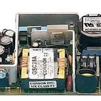
GSC25DG
Description
Linear & Switching Power Supplies 25W +5.1/+24/-12V
Manufacturer
SL Power
Series
GSCr
Datasheet
1.GSC25AG.pdf
(2 pages)
Specifications of GSC25DG
Product
Switching
Commercial/medical
Commercial
Output Power Rating
13 W
Input Voltage
90 VAC to 264 VAC
Number Of Outputs
3
Output Voltage (channel 1)
5.1 V
Output Current (channel 1)
2.5 A
Output Voltage (channel 2)
24 V
Output Current (channel 2)
1 A
Output Voltage (channel 3)
- 12 V
Output Current (channel 3)
0.2 A
Mounting Style
Chassis
Dimensions
4.25 in L x 2.5 in W x 0.86 in H
Open Frame/enclosed
Open Frame
Output Type
Triple Output
Lead Free Status / RoHS Status
Lead free / RoHS Compliant


SL Power Electronics Corp. 6050 King Drive, Bldg. A, Ventura, CA 93003, USA. Phone:(805) 486 4565 Fax:(805) 487 8911 Email: info@slpower.com Rev. 4/22/08.
Data Sheet © 2008 SL Power Electronics Corp. The information and specifications contained in this data sheet are believed to be correct at time of publication.
However, SL Power Electronics accepts no responsibility for consequences arising from reproduction errors or inaccuracies. Specifications are subject to change without
notice.
GSC25/GSM25 MECHANICAL SPECIFICATIONS
ENVIRONMENTAL SPECIFICATIONS
Temperature (A)
Humidity (A)
Shock (B)
Altitude
Vibration (C)
Commercial
A. To maintain proper regulation on output 2, +5.1 V current must be at least 1⁄4 and not greater than 5 times V2 current. V1 must be adjusted within 1% of 5.1 V
to maintain full load regulation on V2.
B. Thermal foldback type current limit
C. Add “G” suffix to model number for RoHS compliant model.
GSC25A
GSC25D
GSC25B
Model
GSM25D
GSM25A
GSM25B
Medical
Model
Output No.
OPERATING
See individual specs.
0 to 95% RH
20 g
-500 to 10,000 ft
1.5 g
1
2
3
1
2
3
1
2
3
pk
rms’
0.003 g
2
Output
/Hz
+ 5.1 V
+12 V
+15 V
- 15 V
+5.1 V
- 12 V
+24 V
+ 5 V
-12 V
NON-OPERATING
-40 to +85°C
0 to 95% RH
40 g
-500 to 40,000 ft
5 g
rms’
pk
0.026 g
Current
2.5 A
1.5 A
0.2 A
2.5 A
1.5 A
0.2 A
2.5 A
1.0 A
0.2 A
2
/Hz
Regulation
A. Units should be allowed to warm up/operate under
non-condensing conditions before application of power.
B. Shock testing—half-sinusoidal, 10 ± 3 ms duration, ± direction,
3 orthogonal axes, total 6 shocks.
C. Random vibration—10 to 2000Hz, 6dB/octave roll-off from 350
to 2000Hz, 3 orthogonal axes. Tested for 10 min./axis operating and
1 hr./axis non-operating.
Load
1%
4%
1%
1%
4%
1%
1%
4%
1%
Initial Setpoint
Tolerance
1%
3%
4%
1%
3%
4%
1%
3%
4%
6.2 ± 0.6 V
6.2 ± 0.6 V
6.2 ± 0.6 V
Setting
OVP
Ripple and
Noise
1%
1%
1%
1%
1%
1%
1%
1%
1%
Notes
A
A
B
A
A
B
A
A
B
Related parts for GSC25DG
Image
Part Number
Description
Manufacturer
Datasheet
Request
R

Part Number:
Description:
POWER SUPPLY SWITCHER 20W TRIPLE
Manufacturer:
SL Power Electronics Manufacture of Condor/Ault Brands
Datasheet:
Part Number:
Description:
POWER SUPPLY, SWITCHING; 0.6 A (MAX.); 15 MS (MIN.); 0 TO 50 DEGC
Manufacturer:
SL Power ( Ault / Condor )
Datasheet:
Part Number:
Description:
Gsc25 Commercial/gsm25 Medical 25 Watt Global Performance Switchers
Manufacturer:
SL Power Electronics
Datasheet:

Part Number:
Description:
LEAD, IEC C19 TO EURO PLUG, 1M
Manufacturer:
MULTICOMP
Datasheet:
Part Number:
Description:
LEAD, IEC C19 TO EURO PLUG, 2M
Manufacturer:
MULTICOMP
Datasheet:
Part Number:
Description:
LEAD, IEC C19 TO EURO PLUG, 3M
Manufacturer:
MULTICOMP
Datasheet:
Part Number:
Description:
LEAD, IEC C19 UK PLUG, 1M
Manufacturer:
MULTICOMP
Datasheet:
Part Number:
Description:
LEAD, IEC C19 UK PLUG, 3M
Manufacturer:
MULTICOMP
Datasheet:
Part Number:
Description:
LEAD, IEC C19 TO BARE ENDS, 1M
Manufacturer:
MULTICOMP
Datasheet:
Part Number:
Description:
LEAD, IEC C19 BARE ENDS, 2M
Manufacturer:
MULTICOMP
Datasheet:

Part Number:
Description:
50W, 36-75Vin, Single, 2.5V@20A, 1/16 Brick Open Frame, 89% Eff, Pos, SMT, RoHS 6
Manufacturer:
Emerson Network Power
Datasheet:
Part Number:
Description:
System Power Supplies
Manufacturer:
SL Power Electronics
Datasheet:
Part Number:
Description:
Switching Power Supply Modules
Manufacturer:
SL Power Electronics
Datasheet:
Part Number:
Description:
Cent1120 Universal 120 Watt Series
Manufacturer:
SL Power Electronics
Datasheet:
Part Number:
Description:
Gpfc110 Commercial 110 Watt Global Performance Switchers
Manufacturer:
SL Power Electronics
Datasheet: