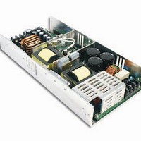
USP-500-5 Mean Well, USP-500-5 Datasheet - Page 3

USP-500-5
Manufacturer Part Number
USP-500-5
Description
Linear & Switching Power Supplies 5V 80A 300W Active PFC Function
Manufacturer
Mean Well
Datasheet
1.USP-500-48.pdf
(4 pages)
Specifications of USP-500-5
Product
Switching
Commercial/medical
Commercial
Output Power Rating
400 W
Input Voltage
90 VAC to 264 VAC, 127 VDC to 370 VDC
Number Of Outputs
1
Output Voltage (channel 1)
5 V
Output Current (channel 1)
80 A
Mounting Style
Chassis
Output Type
DC
Lead Free Status / RoHS Status
Lead free / RoHS Compliant
1.Remote Control
2.DC-OK Signal
The PSU can be turned ON/OFF by using the
Function Description of CN50
Function Manual
"Remote Control" function.
DC-OK signal is a TTL level signal. High when PSU turns on.
SW OFF (0 ~ 0.8V)
SW ON (4 ~ 10V)
3.3 ~ 5.6V
0 ~ 1V
Between RC+(pin4) and RC-(pin3)
Between DC-OK(pin6) and GND(pin5)
Pin No. Function Description
2,8
1
3
4
5
6
7
(Optional)
DC-OK
GND
RC+
RC-
CS
+S
-S
500W Single Output with PFC Function
Current sharing signal. When units are connected in parallel, the CS pins of the units should be connected to allow current balance
between units.
Negative sensing. The -S signal should be connected to the negative terminal of the load. The -S and +S leads should be twisted in pair to
minimize noise pick-up effect. The maximum line drop compensation is 0.5V.
Return for RC+ signal input.
Turns the output on and off by electrical or dry contact between pin 4 ( RC+) and pin 3 (RC-). 0~0.8V: Power ON, 4~10V: Power OFF.
This pin connects to the negative terminal (-V). Return for DC_OK signal output.
DC-OK signal is a TTL level signal, referenced to pin6(DC-OK GND). High when PSU turns on.
Positive sensing. The +S signal should be connected to the positive terminal of the load. The +S and -S leads should be twisted in pair to
minimize noise pick-up effect. The maximum line drop compensation is 0.5V.
Output Status
Output Status
OFF
OFF
ON
ON
CN50
CN50
LED
LED
1
2
1
2
8
8
7
7
+V
+V
+
LOAD
Fig 1.1
Fig 2.1
TB2
TB2
-
-V
-V
U S P - 5 0 0
External Power
Source
File Name:USP-500-SPEC 2010-10-18
NC
NC
-S
-S
1
2
1
2
RC+
RC+
RC-
RC-
CN50
CN50
I=6~20mA
SW
DC-OK
DC-OK
GND
GND
s e r i e s
+S
+S
-S
-S
7
8
7
8


