1210B Staco Energy Products Company, 1210B Datasheet - Page 4
1210B
Manufacturer Part Number
1210B
Description
Transformers OPEN 0-120V 12A
Manufacturer
Staco Energy Products Company
Type
Variable Transformersr
Datasheet
1.1210B.pdf
(4 pages)
Specifications of 1210B
Dimensions
4.16 in L x 4.62 in W x 5.57 in H
Product
Variable Transformers
Height
5.57 in
Length
4.16 in
Width
4.62 in
Input Voltage
120V
Output Current
12A
Knob Rotation
CW / CCW
Transformer Mounting
Bench
Secondary Current Nom
12A
No. Of Phases
Single
Primary Voltages
120V
Power Rating
1.44kVA
Constant Current Load
12A
Rohs Compliant
Yes
Current Rating
12A
Leaded Process Compatible
No
Output Voltage
120V
Lead Free Status / RoHS Status
Lead free / RoHS Compliant
Lead Free Status / RoHS Status
Lead free / RoHS Compliant, Lead free / RoHS Compliant
Available stocks
Company
Part Number
Manufacturer
Quantity
Price
Company:

Part Number:
1210B103K102N
Manufacturer:
WALSIN
Quantity:
600 000
Company:
Part Number:
1210B104K101CT
Manufacturer:
Walsin
Quantity:
3 409
Company:
Part Number:
1210B104K101N
Manufacturer:
WALSIN
Quantity:
600 000
Company:
Part Number:
1210B104K201CT
Manufacturer:
Walsin
Quantity:
2 269
Company:
Part Number:
1210B105K101CT
Manufacturer:
WALSIN
Quantity:
400 000
Part Number:
1210B225K250CT
Manufacturer:
WALSIN
Quantity:
20 000
Part Number:
1210B225K500NT
Manufacturer:
FH/风华高科
Quantity:
20 000
Part Number:
1210B475K500NT
Manufacturer:
FH原装
Quantity:
20 000


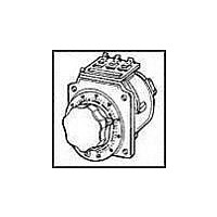
The 1210B operates on 120 volts and is rated for constant
current of 12 amperes. The 1220B operates on 240 volts and
constant current of 5 amperes. The 1210B and 1220B oper-
ate from 0 to line voltage only. There is no reduction in allow-
able output current up to 1500 hertz.
Uncased models have the shaft extending from the base
end. This shaft is fully adjustable and can be extended from
either end for general utility mounting. Cased styles, which
have a “CT” suffix, feature the protective screening over the
coil assembly and a terminal box cover with knock-outs to
•
++ Line to line voltage
‡
†
π
#
M1210BCT-2†
M1210BCT-3†
M1220BCT-2†
M1220BCT-3†
M1210BCT†
M1220BCT†
M1210B-2†
M1210B-3†
M1220B-2†
M1220B-3†
1200 Series
PART NO.
1210BCT-2
1210BCT-3
1220BCT-2
1220BCT-3
3PN1210B
3PN1220B
M1210B†
M1220B†
1210BCT
1220BCT
1210B-2
1210B-3
1220B-2
1220B-3
1210B
1220B
Jumper provided in the standard common position and should be moved or removed as required.
Unit is fused for the constant current rating at the factory.
Motor driven units use terminal connections for CCW increasing voltage, as viewed from the base end. See Figure 23 on page 9 for motor wiring.
If ganged units are used in a system that ordinarily has a common neutral or ground between source and load, the neutral or ground must be connected to the common terminals
of the variable transformer assembly. If the system has no neutral, the load must be balanced or the transformers will be damaged.
Maximum output current in output voltage range from 0 to 25% above line voltage. At higher output voltages, the output current must be reduced according to the derating curve,
Figure B, page 6.
WIRING
Delta π
Delta π
Phase
Phase
Series
Phase
Phase
Phase
Phase
Phase
Series
Phase
Phase
Phase
Single
Single
Three
Three
Wye π
Single
Single
Single
Three
Three
Wye π
Single
Open
Open
VOLTS
120++
240++
240++
480++
120
240
120
240
480
240
INPUT
HERTZ
60
60
60
60
60
60
60
60
60
60
VOLTS
0-120
0-240
0-120
0-240
0-120
0-240
0-480
0-240
0-480
0-240
AMPS
5.0‡
12‡
MAX
5.0
5.0
5.0
5.0
12
12
12
12
CONSTANT
CURRENT
LOAD
OUTPUT
MAX
1.44
2.88
2.49
4.96
1.44
1.20
2.40
2.08
4.16
1.20
KVA
AMPS
MAX
7.0
7.0
7.0
7.0
7.0
15
15
15
15
15
IMPEDANCE
CONSTANT
LOAD
accept conduit.
Motor driven units are available in single, two and three
ganged assemblies; cased or uncased styles as identified by
the prefix “M” in the type number. If a motor driven model is
ordered, be sure to prefix the part number with the desired
travel time from 0 to maximum of 5, 15, 30, or 60 seconds.
The synchronous motor is designed for operation on 120
volts, 50/60 hertz single phase lines and draws approximately
0.3 amperes.
MAX
KVA
1.80
3.60
3.12
6.24
1.80
1.68
3.36
2.91
5.82
1.68
INCREASE
ROTATION
VOLTAGE
SHAFT
CCW
CCW
CCW
CCW
CCW
CCW
CCW
CCW
FOR
CW
CW
CW
CW
CW
CW
CW
CW
CW
CW
TERMINAL CONNECTIONS
Input
1-4-1
4-1-4
1-1-1
4-4-4
1-4-1
4-1-4
1-1-1
4-4-4
1-4
1-4
1-1
4-4
1-4
1-4
1-1
4-4
As Viewed from Base End
(For increasing Voltage)
RECEPTACLE
RECEPTACLE
LINE CORD &
LINE CORD &
Jumper• Output
4-4-4
1-1-1
4-4-4
1-1-1
4-4
1-1
4-4
1-1
4-4
1-1
4-4
1-1
—
—
—
—
3-4-3
3-1-3
3-3-3
3-3-3
3-4-3
3-1-3
3-3-3
3-3-3
4-3
1-3
3-3
3-3
4-3
1-3
3-3
3-3
(Pg 8 & 9)
SCHE-
MATIC
13 & 4
13 & 5
13 & 6
13 & 4
13 & 5
13 & 6
13
11
13
11
10 1/4 16 3/4
22 1/2 30 3/4
34 1/2 42 1/4
10 1/4
10 1/4 16 3/4
22 1/2 30 3/4
34 1/2 42 1/4
10 1/4
LBS. DRIVEN
NET
WT.
MOTOR
(Max)
—
—
Related parts for 1210B
Image
Part Number
Description
Manufacturer
Datasheet
Request
R

Part Number:
Description:
STACO MOTORIZED VARIABLE TRASFORMER 480V INPUT 480/5 10 AMPS SPEED 15 SECONDS 2 GANG UNIT
Manufacturer:
Staco Energy Products Company

Part Number:
Description:
Transformers TRANS 0-120V 1.75A
Manufacturer:
Staco Energy Products Company
Datasheet:
Part Number:
Description:
Transformers TRANS VAR 0-120V 3A
Manufacturer:
Staco Energy Products Company
Datasheet:

Part Number:
Description:
Transformers 120Vin 2.0A 0-120/0-132 Vout
Manufacturer:
Staco Energy Products Company
Datasheet:
Part Number:
Description:
Transformers 240Vin 0.8A 0-240/0-264 Vout
Manufacturer:
Staco Energy Products Company
Datasheet:

Part Number:
Description:
Variable Transformer
Manufacturer:
Staco Energy Products Company
Datasheet:
Part Number:
Description:
Variable Transformer
Manufacturer:
Staco Energy Products Company
Datasheet:

Part Number:
Description:
Variable Transformer
Manufacturer:
Staco Energy Products Company
Datasheet:

Part Number:
Description:
Variable Transformer
Manufacturer:
Staco Energy Products Company
Datasheet:
Part Number:
Description:
Variable Transformer
Manufacturer:
Staco Energy Products Company
Datasheet:
Part Number:
Description:
Transformers TRANS VAR 0-120V 3A
Manufacturer:
Staco Energy Products Company
Datasheet:
Part Number:
Description:
Transformers 120Vin 2.0A 0-120/0-132 Vout
Manufacturer:
Staco Energy Products Company
Datasheet:
Part Number:
Description:
Variable Transformer
Manufacturer:
Staco Energy Products Company
Datasheet:
Part Number:
Description:
VOLTAGE REGULATORS
Manufacturer:
Staco Energy Products Company
Part Number:
Description:
Transformers 240/120 10A W/Screening
Manufacturer:
Staco Energy Products Company
Datasheet: