FLUKE-123/003 Fluke, FLUKE-123/003 Datasheet - Page 5
FLUKE-123/003
Manufacturer Part Number
FLUKE-123/003
Description
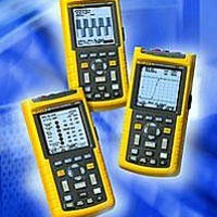
Handheld Oscilloscopes INDUST SCOPEMETER
Manufacturer
Fluke
Type
Digitalr
Datasheet
1.FLUKE-199C003S.pdf
(8 pages)
Specifications of FLUKE-123/003
Display
102 mm Monochrome LCD
Sampling Rate
1.25 GS/s
Bandwidth
20 MHz
Brand/series
ScopeMeter®/120 Series
Configuration
Handheld
Dimensions
232 mm x 115 mm x 50 mm
Display Type
Monochrome LCD
Interface
RS-232
Memory
512 pts
Number Of Channels
2
Sample Rate
0.025 GS/s
Voltage Range
600 V
10
1 Voltage Probe Included with Fluke 124 for Reduced Circuit Loading
Lead Free Status / RoHS Status
Lead free / RoHS Compliant
Other names
2063915


Connect-and-View: Advanced automatic triggering
that recognizes signal patterns and automatically sets
up and continuously adjusts triggering, time base and
amplitude. Automatically displays stable pictures of
complex and dynamic signals like motor drive and
control signals
Video triggering: NTSC, PAL, PAL+, SECAM. Includes
line select
Time delay: Up to 10 divisions pre-trigger view
Measurements
Vdc, Vac, Vac+dc, Vpeak max, Vpeak min, Vpeak
to peak, frequency (Hz), positive pulse width, negative
pulse width, positive duty cycle, negative duty
cycle, Amp ac, Amp dc, Amp ac+dc, Phase,
Temperature °C, Temperature °F, dBV, dBm into 50 W
and 600 W. (Amps, °C or °F with optional probes)
Cursor measurements (125, 124)
Sources: Input A, Input B
Modes: Single or dual vertical cursor, dual horizontal
cursor, risetime or falltime
Measurements:
Single vertical line: Average, min value, max value,
time from start of recording in roll mode
Dual vertical lines: ∆V at markers, time between
cursors, 1/T between cursors (in Hz)
Dual horizontal lines: High, low or ∆V – readout,
risetime and falltime: transition time, 0 %-level,
100 %-level, with markers at 10 % and 90 %
Accuracy: As oscilloscope
Bus health tester (Fluke 125 only)
Bus health automatically analyzes the electrical signals
on the network to give waveform data and measure
individual parameters. Automatic comparison of the
measurement results to the standards results in “good”
or “false” indicators to be displayed per parameter.
Bus types and reference standards used:
AS-i (EN50295, 166 kb/s)
CAN-bus (ISO-11898, up to 1 Mb/s);
Interbus S (EIA-485, up to 10 Mb/s)
ControlNet (61158 type 2, 2.5 Mb/s)
Modbus (EIA-232, up to 115 kb/s and
EIA-485, up to 10 Mb/s)
Foundation Fieldbus H1 (61158 type 1, 31.25 kb/s)
and H2 (61158 type 1, up to 10 Mb/s);
Profibus DP (EIA-485, up to 10 Mb/s) and
PA (61158 type 1, 31.25 kb/s);
Ethernet [10Base2 (coaxial) and 10BaseT
(UTP)], 10 Mb/s;
RS-232 (EIA-232, up to 115 kb/s);
RS-485 (EIA-485, up to 10 Mb/s);
or user defined system
Measured parameters: Baud rate, risetime, falltime,
high level, low level, distortion, amplitude and jitter,
with comparison to system’s standard values
Power measurements (Fluke 125 only)
Measure types: Watt, VA, VAR, Power Factor (PF)
Power configuration: Single phase or balanced
3-phase (delta-configuration) mains supply
Voltage measurement: Channel A, using STL120,
voltage probe or direct input
Current measurement: Channel B, using i400s
current clamp (included) or other compatible clamp
Current clamp sensitivity: 0.1/1/10/100/1000 mV/A,
10 mV/mA and 400 mV/A
®
;
®
;
®
®
;
;
ScopeMeter 190C/190B Series, 120 Series and the NEW ScopeMeter 125
Harmonics mode (Fluke 125 only)
Converts waveform information into a harmonics dis-
play (using FFT processing), which shows the relative
amplitudes of the 1st up to the 33rd harmonic
Harmonics frequency range: DC to 33rd harmonic
(fundamental ≤ 60 Hz); DC to 24th (fundamental
≤ 400 Hz)
Analyzed waveform: Voltage waveform (Ch.A),
current waveform (Ch.B) or power (Ch.A x Ch.B),
automatically generated
Display: Bargraph showing 1st up to 33rd harmonic,
amplitude displayed in % relative to fundamental
Timebase setting: 5 ms/div.
Measurements: Relative amplitude of individual
harmonic; THD in %r or %f
Dual input meter
The specified accuracy is valid over the temperature
range 18 °C to 28 °C (64 °F to 82 °F). Add 10 % of
specified accuracy for each °C below 18 °C or above
28 °C (64 °F to 82 °F)
Max. meter bandwidth: 40 MHz (Fluke 125, 124),
20 MHz (Fluke 123)
Voltage measurements
Measurement selection: Vdc, Vac rms, Vac+dc rms,
Vpeak max, Vpeak min, V
Ranges: 500 mV, 5 V, 50 V, 500 V, 1250 V
Full scale reading: 5,000 counts
Accuracy
Ohms
Ranges: 500 W, 5 kW, 50 kW, 500 kW, 5 MW, 30 MW
(all models), 50.00 W (Fluke 125 only)
Max. resolution: 5,000 counts
Accuracy: ± (0.6 % of reading + 5 counts)
Capacitance
Ranges: 50 nF to 500 µF
Max. resolution: 5,000 counts
Accuracy: ± (2 % of reading + 10 counts)
Other meter functions
Frequency: Up to 70 MHz (Fluke 125, 124) or up to
40 MHz (Fluke 123)
Rotational speed (RPM): Revolutions per minute,
based on 1, 2 or 4 or 8 pulses per 2 revolutions
(Fluke 125 only)
Max. RPM reading: 50 kRPM
Continuity: Beeper on < 30 W
Diode test: Up to 2.8 V
Amps: Amp dc, Amp ac, Amp ac+dc using an optional
current clamp or shunt. Scaling factors: 0.1 mV/Amp to
100 V/Amp
Vdc: ± (0.5 % + 5 counts)
Vac rms:
Vac+dc true-rms:
Vpeak:
1 Hz to 60 Hz: ± (1 % + 10 counts)
60 Hz to 1 kHz: ± (2.5 % + 15 counts)
20 kHz to 1 MHz ± (5 % + 20 counts)
DC to 60 Hz: ± (1 % + 10 counts)
60 Hz to 1 kHz: ± (2.5 % + 15 counts)
20 kHz to 1 MHz (5 % + 20 counts)
Max peak or Min peak: 5 % of full scale
Peak-to-peak: 10 % of full scale
pk-pk
Fluke Corporation 5