ACA-20RM-2-AC4-RL-C Murata Power Solutions Inc, ACA-20RM-2-AC4-RL-C Datasheet - Page 4
ACA-20RM-2-AC4-RL-C
Manufacturer Part Number
ACA-20RM-2-AC4-RL-C
Description
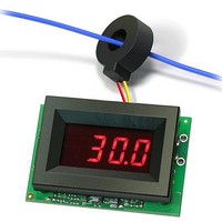
Digital Panel Meters 19.99AInput TrueRMS-AC
Manufacturer
Murata Power Solutions Inc
Type
AC Ammetersr
Datasheet
1.ACA-20RM-5-AC3-RL-C.pdf
(5 pages)
Specifications of ACA-20RM-2-AC4-RL-C
Equipment Type
AC Ammeters
Display Type
3 - 1/2 Digit LED
Primary Voltage Rating
170 V to 264 V
Secondary Current Rating
50 mA
No. Of Digits / Alpha
3.1/2
Meter Function
AC Ammeter
Meter Range
0A To 19.99A
Digit Height
9.4mm
Supply Voltage Range
170VAC To 264VAC
Operating Temperature Range
0°C To +60°C
Meter Signal Input
Current
Lead Free Status / RoHS Status
Lead free / RoHS Compliant


BEZEL AND PANEL CUTOUT
PANEL INSTALLATIONS
All connections to ACA-20RM Series ammeters must be made after the
ammeter is securely attached to its panel and with all associated load
and supply voltages de-energized (off). However, using extreme caution
and observing all safety measures applicable to the user’s installation,
50A split-core CT models can be connected to energized current-carry-
ing load conductors, but connections to TB1 must always be made with
the ammeter’s power source off.
Care should be exercised when passing the load-carrying conductor
through the meter’s built-in CT---particularly when larger conductors are
used. The installed wire-positions should be such that minimal mechani-
cal forces are applied to the built-in CT, TB1, or to the ammeter itself. In
high-vibration environments, it is strongly recommended that adequate
strain reliefs be used for all load and supply wiring.
FRONT V IEW
1.826 ( 46.38)
(4.75)
0.187
PANEL
(32.51)
1.280
www.murata-ps.com/dpm
Figure 4. Panel Installation
(17.5)
0.69
(27.18)
0.093 ( 2.362) D IAMETER ( 4 R EQUIRED)
Using Figure 4 as a guide, carefully insert the bezel/color fi lter assembly
into the panel opening. From the rear of the panel, install the four round
plastic standoffs over the bezel’s threaded studs. Install the pc-board
assembly then attach and securely tighten all four hex nuts. Use only
the factory-supplied hardware as the use of substitute hardware could
result in an unsafe installation and/or adversely affect the reliability of
the ammeter itself.
The recommended range of panel thickness that can be used with the
supplied hardware is 0.040 inches (1.0mm) to 0.125 inches (3.2mm).
Panel thickness outside of this range will require additional user-supplied
hardware and/or modifi cations.
1.07
INTERNAL C ORNER R ADII:
True-RMS-AC Ammeters with Built-in CT
PANEL C UTOUT D IMENSIONS
RECOMMENDED D RILL A ND
0.032 ( 0.81) M AX.
1.336 ( 33.93)
1.626 ( 41.30)
26 Jan 2011 MPM_ACA-20RM_B05 Page 4 of 5
ACA-20RM Series
email: sales@murata-ps.com
0.145 ( 3.68)
0.116 ( 2.95)
(21.29)
0.838