H7CX-A114D1-N-DC12-24/AC24 Omron, H7CX-A114D1-N-DC12-24/AC24 Datasheet - Page 28
H7CX-A114D1-N-DC12-24/AC24
Manufacturer Part Number
H7CX-A114D1-N-DC12-24/AC24
Description
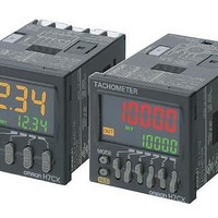
Tachometers 11-pin SPDT 4 Digits 12-24VDC/VAC24
Manufacturer
Omron
Type
1 Stage and Total Preset Counterr
Datasheet
1.H7CX-A-N_AC100-240.pdf
(56 pages)
Specifications of H7CX-A114D1-N-DC12-24/AC24
Frequency Response
50 Hz
Product
Panel Mount Tachometer
Voltage
12 VDC to 24 VDC
Display Type
4 Digit
Accuracy
+/- 0.1 %
Lead Free Status / RoHS Status
Lead free / RoHS Compliant
Other names
DC1224/AC24 H7CXA114D1N H7CXA114D1NDC1224/AC24


28
H7CX-A@-N
Tachometer
From next page
Change to Function Setting Mode.
Step3
*1 If the mode is switched to the function setting mode during operation, operation will continue.
*2 Changes made to settings in function setting mode are enabled for the first time when the mode is changed to run mode.
Also, when settings are changed, the counter is reset (measured value initialized and outputs turned OFF) on returning to run mode.
Run mode
Power ON
To next page
Parameters that cannot be set with the DIP switch are set with the operation keys on the front panel.
Tachometer
output mode
(TOTM)
Auto-zero
time
(AUT00)
Average
processing
(AVGN)
Counting
speed
(CNTS)
Decimal point
position
(DP)
Prescale
value
(PSCL)
Startup time
(STMR)
Tachometer
input mode
(TINM)
Averaging
method
(AVGT)
3 s min.
3 s min.
*1
setting mode
*1
*2
Function
The characters displayed in reverse video are the default settings.
When performing settings with operation keys only, set pin1 of the DIP switch to OFF (factory setting).
If pin 1 of the DIP switch is set to ON, the setting items indicated by
• Set the tachometer input mode using the U Key.
• Set the tachometer output mode using the U Key.
• Set the decimal point position using the U Key.
• Set each digit using the individual U Key.
• Set the counting speed using the U Key.
Note: Even if 10 kHz is selected when the tachometer input mode is F2 to F5, the counting speed will be 5 kHz.
Note: “--.----“ will be displayed when pulse width measurement is set or when the display unit is set to seconds.
• Set the number of averaging times using the U Key.
• Set each digit using the individual U Key.
• Set the averaging method using the U Key.
• Set each digit using the individual U Key.
(No decimal point) (One digit after
averaging)
(No average
(1 input) (2 inputs)
processing)
(0.1 s)
(0.0 s)
(HI-LO)
(Simple
(0.001)
(30 Hz)
0.001
hilo
30hz
0.1
0.0
f1
smp
off
(99.9 s)
(999.9 s)
measurements)
999.9
99.9
(Average of 2
For details on operations and display in run mode, refer to page page 33.
(10 kHz)
(Moving
average)
f2
(AREA)
1.000
(1.000)
area
mv
2
decimal point)
(Error) (Absolute ratio)
f3
measurements)
(Average of 4
99.999
(99.999)
(HI-HI)
hihi
4
(Two digits after
f4
decimal point)
(LO-LO)
measurements)
(Average of 8
lolo
8
(Error ratio)
f5
(Three digits after
(Average of 16
measurements)
decimal point)
16
(Four digits after
decimal point)
*1 Set tachometer output modes 1 and 2 using the
* Displayed only when the tachometer input mode is F2
--.----
(2 inputs).
U Key.
will not be displayed.
Tachometer
output
mode 1
(TO1M)
Tachometer
output
mode 2
(TO2M)
(HI)
(HI)
hi
hi
(LO)
(LO)
lo
lo