H7CX-A11D1-N DC12-24/AC24 Omron, H7CX-A11D1-N DC12-24/AC24 Datasheet - Page 36
H7CX-A11D1-N DC12-24/AC24
Manufacturer Part Number
H7CX-A11D1-N DC12-24/AC24
Description
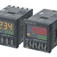
Tachometers 11-pin SPDT 6 Digits 12-24VDC/VAC24
Manufacturer
Omron
Type
1 Stage and Total Preset Counterr
Specifications of H7CX-A11D1-N DC12-24/AC24
Frequency Response
50 Hz
Product
Panel Mount Tachometer
Voltage
12 VDC to 24 VDC, 24 VAC
Display Type
6 Digit
Accuracy
+/- 0.1 %
No. Of Digits / Alpha
6
Digit Height
10mm
Power Consumption
4.7W
Counting Speed
5kHz
Operating Temperature Range
-10°C To +55°C
Meter Function
Counter
Signal Input Type
PNP/NPN
Character Size
9mm
Supply Voltage Min
12VDC
Rohs Compliant
Yes
Connector Type
11-Pin Socket
Lead Free Status / RoHS Status
Lead free / RoHS Compliant
Lead Free Status / RoHS Status
Lead free / RoHS Compliant, Lead free / RoHS Compliant


36
H7CX-A@-N
Key Protect Level
It is possible to prevent setting errors by prohibiting the use of certain operation keys by specifying the key protect level (KP-1 to KP-7) when the
key-protect switch is set to ON.
The key protect level is set in the function setting mode. The key protect indicator is lit when the key-protect switch is ON.
* Changing mode to configuration selection mode or function setting mode.
Self-diagnostic Function
The following displays will appear if an error occurs.
*1. Displays for 4-digit models are given in parentheses.
*2. This includes times when the life of the EEPROM has expired.
*3. This occurs if the present value or total count value falls below 99999
*4. This occurs in the following conditions if the present value (i.e.,
*5. Display flashes.(1-second cycles)
*6. This does not apply when tachometer operation is used.
(default setting)
-----
fffff
( 999 for 4-digit models).
measurement value) exceeds 999999 (9999 for 4-digit models).
For Output Modes K-2, D, L, or H
Dual counter or tachometer operation is used.
Main display
Level
KP-1
KP-2
KP-3
KP-4
KP-5
KP-6
KP-7
(
(
e3*8
e1
e2
e2
----
ffff
)*1*5
)*1*5
Sub-display
No change
No change
No change
Description
Not lit
Not lit
sum
*Factory-set to OFF
(Disable)
*
OFF
Present value underflow*3
Present value overflow*4
CPU error
Memory error (RAM)
Memory error (EEPROM)*2
Output Counter Overflow
Key protect indicator
Description
ON
(Enable)
Changing modes*
Invalid
Invalid
Invalid
Invalid
Invalid
Invalid
Invalid
Output status
No change
No change
No change
*7. This is displayed if the alarm value setting for either of the two outputs is
*8. The normal display and e3 will appear alternately.
OFF
OFF
OFF
exceeded if a model with two outputs is used.The total ON count will not be
cleared by using the Reset Key.
When the Reset Key is pressed, e3 will not be displayed even if the alarm
set value is exceeded.
(Monitoring is possible, however, because the counter will continue without
the output ON count being cleared.)
Switching display
during operation
Invalid
Invalid
Invalid
Valid
Valid
Valid
Valid
Either press the Reset Key or turn
ON reset input.
Either press the Reset Key or turn
ON reset input.*6
Either press the Reset Key or
reset the power supply.
Turn ON the power again.
Reset Key
Reset Key*7
Details
Correction method
Reset Key
Invalid
Invalid
Invalid
Invalid
Valid
Valid
Valid
Set value after reset
Up/Down Keys
Factory setting
No change
No change
No change
No change
No change
Invalid
Invalid
Invalid
Valid
Valid
Valid
Valid