145-0701-602 Emerson Network Power, 145-0701-602 Datasheet - Page 2
145-0701-602
Manufacturer Part Number
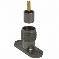
145-0701-602
Description
CONN SMK JACK RCPT 2-HOLE FLANGE
Manufacturer
Emerson Network Power
Series
SMKr
Datasheet
1.145-0701-602.pdf
(2 pages)
Specifications of 145-0701-602
Connector Style
SMK
Connector Type
Jack, Female Sockets
Contact Termination
Solder
Impedance
50 Ohm
Mounting Type
Panel Mount, Flange (2 Hole)
Fastening Type
Threaded
Frequency - Max
40GHz
Frequency-max
40GHz
Body Style
Flange
Features
2 Hole Flange
Frequency Range
0 Hz to 40 GHz
Length
2.92 mm
Rf Series
SMK
Product
Various Connectors
Gender
Female
Shell Plating
Passivated
Termination Style
Solder Lug
Maximum Frequency
40 GHz
Lead Free Status / RoHS Status
Lead free / RoHS Compliant
Color
-
Cable Group
-
Lead Free Status / Rohs Status
Lead free / RoHS Compliant
Other names
J692


Impedance: 50 ohms
Frequency Range:
VSWR: (f = GHz)
Working Voltage:
Connectors for Cable T
Dielectric Withstanding Voltage:
Corona Level: (Volts minimum at 70,000 feet)
Insertion Loss:
Insulation Resistance:
Contact Resistance:
RF Leakage:
RF High Potential Withstanding Voltage:
and 7 MHz)
Temperature Range:
Thermal Shock:
Corrosion: MIL-STD-202, Method 101, Condition B
Shock: MIL-STD-202, Method 213, Condition I
Vibration: MIL-STD-202, Method 204, Condition D
Moisture Resistance:
SMK - 50 Ohm Connectors (2.92mm)
INCHES (MILLIMETERS)
Semi-rigid straight cabled connectors and adapters .............. 1.20 Max
Field replaceable ( see typical return loss graph) ............................
.086 semi-rigid and eld replaceable......................... 335
.141 semi-rigid and adapters ..................................... 500
.086 semi-rigid and eld replaceable............................................. 1000
.141 semi-rigid and adapters ......................................................... 1500
.086 semi-rigid and eld replaceable............................................... 250
.141 semi-rigid and adapters ........................................................... 375
Adapters ................................................ 0.06
Straight semi-rigid cable connectors ....... 0.03 f (GHz), tested at 10 GHz
Center contact straight cabled connectors ... 3.0*
Center contact adapters ................................ 4.0
Field replaceable connectors ........................ 6.0
Outer contact (all connectors) ....................... 2.0
Body to cable (gold plated connectors) ......... 0.5
Body to cable (passivated connectors) ......... 5.0
.086 semi-rigid and eld replaceable.............................................. 670
.141 semi-rigid and adapters ........................................................ 1000
(Meets or exceed the applicable paragraph of MIL-C-39012)
=
FIELD REPLACEABLE TEST ASSEMBLY
(dB minimum, tested at 2.5 GHz) ............................. -90dB
•
(dB maximum)
MIL-STD-202, Method 107, Condition B
299 Johnson Avenue SW, Waseca, MN 56093 • 800 -247- 8256 • +1 (507) 833-8822 • www.EmersonConnectivity.com
(Vrms maximum)
0-40 GHz
ENVIRONMENTAL RATINGS
(milliohms maximum) Initial After Environmental
- 65 °C to + 165 °C
MIL-STD-202, Method 106
ELECTRICAL RATINGS
5000 megohms minimum
ype
(VRMS minimum at sea level)
f (GHz), tested at 6 GHz
(Vrms minimum, tested at 4
Emerson Network Power Connectivity Solutions
Sea Level
6.0
8.0
N/A
N/A
N/A
125
4.0
85
70K Feet
N/A
The eld replaceable connectors manufactured by Johnson Components
are easy to install and replace. The hermetic seal is mounted into the circuit
module wall and the connector can be removed and replaced without de-
stroying the hermeticity of the circuit housing.
The eld replaceable connector creates a transition from microstrip circuitry
to a coaxial transmission line. The SMK (2.92mm) seal pin diameter is .012
(.030) to minimize the capacitive e ects on the circuit trace. For optimum
electrical performance, the transition from the hermetic seal to the microstrip
trace must be properly compensated. Compensation involves adjusting
the microstrip trace width to minimize any impedance discontinuities found
in the transition area.
The plot shown below is representative of the typical return loss of a Johnson
Components
below, a test xture is created using the Johnson Components
metic seal. The xture consists of a suitably thick spacer plate with the
hermetic seal mounted ush to both surfaces. Two connectors are mounted
back to back around the xture and the VSWR of this test assembly is
measured. The calculated return loss trace shown is equivalent to the square
root of the measured VSWR of the test assembly. Since the connectors
tested are of identical design, it can be stated with fair accuracy that the
calculated data shown represents the response of a single eld replaceable
connector and its transition to the hermetic seal.
Although Johnson Components
for eld replaceable connectors, typical connector return loss can be ex-
pected to be less than -20 dB through 40 GHz. A VSWR speci cation is not
stated because an industry standard method for testing eld replaceable
connectors does not exist. The actual performance of the connector is
dependent upon the following:
1. For optimum electrical performance, Johnson Components
2. It is recommended that the hermetic seal be mounted ush with the cir-
3. The transition between the hermetic seal pin and the microstrip trace will
the use of our standard 142-1000-033 hermetic seal with a pin diameter
of .0120 (0.305) +/- .0005 (0.013).
cuit housing. Tolerance variations between the hermetic seal and ma-
chined housing do not always guarantee an optimum transition to the
connector. Some manufacturers recommend an additional counterbore
in the circuit housing to accommodate a solder washer during installation
of the seal. Johnson Components
installation because if the counterbore is not completely lled with solder,
electrical discontinuities may be created.
e ect electrical performance, as stated above. Several di erent meth-
ods of hermetic seal mounting and seal pin to microstrip trace attach-
ment are used in the industry.
™
FIELD REPLACEABLE APPLICATION NOTES
eld replaceable SMK connector. To produce the data shown
™
does not publish a VSWR speci cation
™
does not recommend this type of
™
recommends
™
SMK her-
™
,
Related parts for 145-0701-602
Image
Part Number
Description
Manufacturer
Datasheet
Request
R

Part Number:
Description:
CONN SMK JACK RCPT 4-HOLE FLANGE
Manufacturer:
Emerson Network Power
Datasheet:

Part Number:
Description:
CONN SMK JACK RECEPT THREAD MNT
Manufacturer:
Emerson Network Power

Part Number:
Description:
RF Connectors 2HOLE FLANGE JCK GLD
Manufacturer:
Emerson Network Power

Part Number:
Description:
RF Connectors THREAD MOUNT JCK GLD
Manufacturer:
Emerson Network Power

Part Number:
Description:
RF Connectors 4HOLE FLANGE JCK GLD
Manufacturer:
Emerson Network Power

Part Number:
Description:
AC/DC Front end 12Vo 36A 12Vsb Standard Airflow
Manufacturer:
Emerson Network Power

Part Number:
Description:
POWER SUPPLY DIN 24VDC 10A
Manufacturer:
Emerson Network Power
Datasheet:

Part Number:
Description:
POWER SUPPLY SGL 48VOUT 40W 3X5"
Manufacturer:
Emerson Network Power
Datasheet:

Part Number:
Description:
POWER SUP MED&ITE 48V 45W 2"X4"
Manufacturer:
Emerson Network Power
Datasheet:

Part Number:
Description:
POWER SUPPLY 60W 12V OUT
Manufacturer:
Emerson Network Power
Datasheet:

Part Number:
Description:
POWER SUPPLY 60W 48V OUT
Manufacturer:
Emerson Network Power
Datasheet:

Part Number:
Description:
POWER SUPPLY 60W 15V OUT
Manufacturer:
Emerson Network Power
Datasheet:

Part Number:
Description:
POWER SUPPLY TRPL 3.3/5/12V 40W
Manufacturer:
Emerson Network Power
Datasheet:

Part Number:
Description:
POWER SUPPLY SWITCHER 24V 40W
Manufacturer:
Emerson Network Power
Datasheet:

Part Number:
Description:
Linear & Switching Power Supplies 24V output 25W 2A Medical &Non-Medical
Manufacturer:
Emerson Network Power
Datasheet: