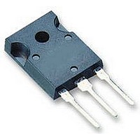
AUIRG4PH50S International Rectifier, AUIRG4PH50S Datasheet

AUIRG4PH50S
Specifications of AUIRG4PH50S
Available stocks
Related parts for AUIRG4PH50S
AUIRG4PH50S Summary of contents
Page 1
... Soldering Temperature, for 10 sec. Mounting Torque, 6- Screw. Thermal Resistance Parameter R Junction-to-Case θJC R Case-to-Sink, Flat, Greased Surface θCS R Junction-to-Ambient, typical socket mount θJA Wt Weight www.irf.com AUTOMOTIVE GRADE AUIRG4PH50S n-channel C TO-247AC G Gate d e 300 (0.063 in. (1.6mm) from case) Min. — — — — ...
Page 2
... AUIRG4PH50S Dynamic Electrical Characteristics @ T Parameter V Collector-to-Emitter Breakdown Voltage (BR)CES V Emitter-to-Collector Breakdown Voltage (BR)ECS Temperature Coeff. of Breakdown Voltage ∆V /∆T (BR)CES J V Collector-to-Emitter Saturation Voltage CE(ON) V Gate Threshold Voltage GE(th) DV /DT Temperature Coeff. of Threshold Voltage GE(th Forward Transconductance fe CES I Gate-to-Emitter Leakage Current ...
Page 3
... Charged Device Model RoHS Compliant www.irf.com † Automotive (per AEC-Q101) Comments: This part number(s) qualification. IR’s Industrial and Consumer qualification level is granted by extension of the higher Automotive level. TO-247AC Class M3 AEC-Q101-002 Class H2 AEC-Q101-001 Class C4 AEC-Q101-005 AUIRG4PH50S †† passed Automotive N/A Yes 3 ...
Page 4
... AUIRG4PH50S 60 40 Square wave: 60% of rated voltage 20 Ideal diodes 0 0.1 Fig Typical Load Current vs. Frequency 1000 ° J 100 T = 150 80µs PULSE WIDTH 1 0.0 1.0 2.0 3 Collector-to-Emitter Voltage (V) CE Fig Typical Output Characteristics 4 For both: Duty cycle: 50 125° 90°C sink Gate drive as specified ...
Page 5
... Fig Maximum Effective Transient Thermal Impedance, Junction-to-Case www.irf.com 2 15V PULSE WIDTH 2.0 1.5 1.0 125 150 -60 -40 -20 ° Fig Typical Collector-to-Emitter Voltage vs. Junction Temperature Notes: 1. Duty factor Peak 0.001 0. Rectangular Pulse Duration (sec) 1 AUIRG4PH50S 16 100 120 140 160 T , Junction Temperature ( C) ° ...
Page 6
... AUIRG4PH50S 7000 1MHz ies 6000 res ies oes ce gc 5000 4000 C oes 3000 C res 2000 1000 Collector-to-Emitter Voltage (V) CE Fig Typical Capacitance vs. Collector-to-Emitter Voltage 25 960V 15V GE ° 33A C 24.0 23.0 22.0 21 Gate Resistance (Ohm) ( Ω Fig Typical Switching Losses vs. Gate ...
Page 7
... R = 5Ohm 150 C ° 960V CC 100 V = 15V Collector Current (A) C Fig Typical Switching Losses vs. Collector-to-Emitter Current www.irf.com 1000 100 10 SAFE OPERATING AREA Fig Reverse Bias SOA AUIRG4PH50S = 20V o = 125 C 10 100 1000 V , Collector-to-Emitter Voltage (V) CE 10000 7 ...
Page 8
... AUIRG4PH50S L 50V 1000V * Driver same type as D.U.T 80% of Vce(max) * Note: Due to the 50V power supply, pulse width and inductor will increase to obtain rated Id. Driver* 50V 1000V Ã 8 D.U. VCC D.U. VCC ICM 480µF Pulsed Collector Current Test Circuit www.irf.com ...
Page 9
... Dimensions are shown in milimeters (inches) www.irf.com AUIRG4PH50S 9 ...
Page 10
... AUIRG4PH50S Ordering Information Base part number Package Type AUIRG4PH50S TO-247AC 10 Standard Pack Complete Part Number Form Quantity Tube 25 AUIRG4PH50S www.irf.com ...
Page 11
... Buyers acknowledge and agree that, if they use any non-designated products in automotive applications, IR will not be responsible for any failure to meet such requirements For technical support, please contact IR’s Technical Assistance Center 233 Kansas St., El Segundo, California 90245 www.irf.com http://www.irf.com/technical-info/ WORLD HEADQUARTERS: Tel: (310) 252-7105 AUIRG4PH50S 11 ...


