138-4449-007 Emerson Network Power, 138-4449-007 Datasheet - Page 21
138-4449-007
Manufacturer Part Number
138-4449-007
Description
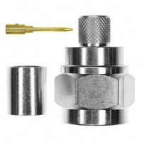
CONN PLUG N STR CRIMP LMR-400
Manufacturer
Emerson Network Power
Series
N Typer
Datasheet
1.138-4701-607.pdf
(24 pages)
Specifications of 138-4449-007
Connector Style
N Type
Connector Type
Plug, Male Pins
Contact Termination
Crimp and Solder
Impedance
50 Ohm
Mounting Type
Free Hanging (In-Line)
Fastening Type
Threaded
Cable Group
Belden 9913, LMR-400
Frequency - Max
11GHz
Frequency-max
11GHz
Body Style
Straight
Cable Type
LMR 400, Belden 9913
Frequency Range
0 GHz to 11 GHz
Mounting Angle
Straight
Rf Series
N
Product
Various Connectors
Gender
Male
Contact Plating
Gold
Shell Plating
Tri Alloy
Termination Style
Crimp
Maximum Frequency
11 GHz
Angle
Straight
Application
Commercial
Primary Type
N
Lead Free Status / RoHS Status
Lead free / RoHS Compliant
Features
-
Color
-
Lead Free Status / Rohs Status
Lead free / RoHS Compliant
Other names
J847


Type N Bulkhead Jack Solder Style for Semi-Rigid Cable
1. Identify connector parts (8 piece parts) and tools (4 piece parts).
2. Strip cable jacket and dielectric to dimension shown. Do not nick
3. Slide stem over cable jacket, keeping stem correctly oriented to end
4. Insert jack contact into rear insulator. Make sure insulator is
5. Slide stem away from jack contact. Insert contact into stop screw
6. Solder jack contact to center conductor through solder hole using
7. After solder joint has cooled, remove cable from vise and remove
8. Slide stem over rear insulator and tighten stem into location fixture
9. Insert cable into vise, but do not clamp. Insert jack contact into stop
10. Solder stem to cable jacket, using a minimum amount of solder for a
11. After solder joint has cooled, un-clamp cable and remove location
12. Add gasket, lock washer and mounting nut when installing
center conductor. Clean all debris from cable.
of cable.
correctly oriented to contact. Place jack contact and rear insulator
onto center conductor, keeping insulator correctly oriented between
cable jacket and contact.
and clamp cable in vise. Tighten stop screw until light pressure is
applied between jack contact, rear insulator and cable jacket.
.020 (.051) diameter flux core solder wire. Use a minimum amount of
solder for a good joint.
any excess solder from jack contact with a sharp blade and clean
all debris from contact and rear insulator.
until stem bottoms out.
screw and tighten location fixture until stop screw bottoms out.
Clamp cable in vise.
full fillet joint. Allow assembly to cool before removing from vise.
fixture from stop screw and cable assembly. Insert front insulator
into bulkhead jack body. Insert cable assembly into body and tighten
to 25-30 in-lbs.
connector to panel.
Connectivity....for
Business-Critical Continuity
Type N Connectors
21
Related parts for 138-4449-007
Image
Part Number
Description
Manufacturer
Datasheet
Request
R

Part Number:
Description:
CONN JACK N SLD 4HOLE FLANGE MT
Manufacturer:
Emerson Network Power
Datasheet:

Part Number:
Description:
AC/DC Front end 12Vo 36A 12Vsb Standard Airflow
Manufacturer:
Emerson Network Power

Part Number:
Description:
POWER SUPPLY SGL 5VOUT 40W 3X5"
Manufacturer:
Emerson Network Power
Datasheet:

Part Number:
Description:
POWER SUPPLY DIN 24VDC 10A
Manufacturer:
Emerson Network Power
Datasheet:

Part Number:
Description:
POWER SUPPLY SGL 48VOUT 40W 3X5"
Manufacturer:
Emerson Network Power
Datasheet:

Part Number:
Description:
POWER SUP MED&ITE 48V 45W 2"X4"
Manufacturer:
Emerson Network Power
Datasheet:

Part Number:
Description:
POWER SUPPLY 60W 12V OUT
Manufacturer:
Emerson Network Power
Datasheet:

Part Number:
Description:
POWER SUPPLY 60W 48V OUT
Manufacturer:
Emerson Network Power
Datasheet:

Part Number:
Description:
POWER SUPPLY 60W 15V OUT
Manufacturer:
Emerson Network Power
Datasheet:

Part Number:
Description:
POWER SUPPLY TRPL 3.3/5/12V 40W
Manufacturer:
Emerson Network Power
Datasheet:

Part Number:
Description:
POWER SUPPLY SWITCHER 24V 40W
Manufacturer:
Emerson Network Power
Datasheet:

Part Number:
Description:
Linear & Switching Power Supplies 24V output 25W 2A Medical &Non-Medical
Manufacturer:
Emerson Network Power
Datasheet:
Part Number:
Description:
Linear & Switching Power Supplies 50W +5/+12/-12VDC
Manufacturer:
Emerson Network Power
Datasheet:
Part Number:
Description:
Linear & Switching Power Supplies 150W 48V 2.1A
Manufacturer:
Emerson Network Power
Datasheet:

Part Number:
Description:
Linear & Switching Power Supplies 600W 24V 0-27A MAX 2.4 x 4.5 x 7.5
Manufacturer:
Emerson Network Power
Datasheet: