138-4694-001 Emerson Network Power, 138-4694-001 Datasheet - Page 20
138-4694-001
Manufacturer Part Number
138-4694-001
Description
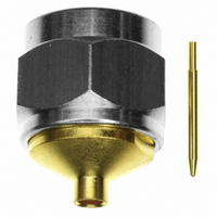
CONN PLUG N STR SOLDER RG-402
Manufacturer
Emerson Network Power
Series
N Typer
Datasheet
1.138-4701-607.pdf
(24 pages)
Specifications of 138-4694-001
Connector Style
N Type
Connector Type
Plug, Male Pins
Contact Termination
Solder
Impedance
50 Ohm
Mounting Type
Free Hanging (In-Line)
Fastening Type
Threaded
Cable Group
RG-402 (.141" Semi Rigid)
Frequency - Max
18GHz
Frequency-max
18GHz
Body Style
Straight
Cable Type
0.141 Semi Rigid
Frequency Range
0 GHz to 18 GHz
Mounting Angle
Straight
Rf Series
N
Product
Various Connectors
Gender
Male
Contact Plating
Gold
Shell Plating
Gold
Termination Style
Solder
Maximum Frequency
18 GHz
Angle
Straight
Application
Commercial
Primary Type
N
Lead Free Status / RoHS Status
Lead free / RoHS Compliant
Features
-
Color
-
Lead Free Status / Rohs Status
Lead free / RoHS Compliant
Other names
J855


Type N Bulkhead Jack Crimp Style for RG-58, 142, 213,
214 and LMR-400 Flexible Cable
1. Identify connector parts (6 piece parts).
2. Strip cable to dimensions shown. Do not nick center
3. Assemble jack contact onto cable as shown. Jack contact
4. Flare braid and slide bulkhead jack connector assembly over
5. Add gasket, lock washer and mounting nut when installing
20
Cable Group
RG-58/U, 141, 303
RG-55/U, 142, 223, 400
RG-8, 213
RG-9, 214
LMR-400, BELDEN 9913
Tool
Crimp Frame
Die Set
conductor. A wire stripper of correct size is recommended for
this step. Tin center conductor if contact will be solder
attached. Do not tin center conductor if contact will be crimp
attached. Slide crimp sleeve onto jacket of cable.
should butt against cable dielectric during attachment.
Solder Attachment: Solder jack contact to center conductor
through solder hole using .020 (.051) diameter flux core solder
wire. Use a minimum amount of solder for a good joint.
Crimp Attachment: Crimp jack contact to center conductor
using Johnson ergonomic hand crimp frame 140-0000-967 with
recommended hex size die set. Crimp location should be on
end of jack contact next to cable dielectric. Crimp attachment
to solid center conductor cables is not recommended.
jack contact and under braid. Seat bulkhead jack connector
assembly firmly onto contact. Arrange braid uniformly around
crimp stem. Slide crimp sleeve forward and crimp using
Johnson ergonomic hand crimp frame 140-0000-967 with
recommended hex size die set. Maintain forward pressure on
cable while crimping.
connector to panel.
Type N Connectors
138-4307-407
138-4308-407
Part No.
138-4316-407
138-4318-407
138-4349-407
Assembly
138-4307/4308-407
140-0000-967
140-0000-990
“A”
.310 (7.87)
.310 (7.87)
.385 (9.78)
.385 (9.78)
.385 (9.78)
138-4316/4318/4349-407
140-0000-967
140-0000-991
.389 (9.88)
“B”
.389 (9.88)
.400 (10.16)
.400 (10.16)
.400 (10.16)
.135 (3.43)
“C”
.135 (3.43)
.165 (4.19)
.165 (4.19)
.165 (4.19)
Crimp Sleeve
Hex Size
.213 (5.41)
.213 (5.41)
.429 (10.90)
.429 (10.90)
.429 (10.90)
Contact
Hex Size
.068 (1.73)
.068 (1.73)
.111 (2.82)
.111 (2.82)
.116 (2.95)
Connectivity....for
Business-Critical Continuity
Related parts for 138-4694-001
Image
Part Number
Description
Manufacturer
Datasheet
Request
R

Part Number:
Description:
CONN PLUG N STR SOLDER RG-402
Manufacturer:
Emerson Network Power
Datasheet:

Part Number:
Description:
CONN JACK N SLD 4HOLE FLANGE MT
Manufacturer:
Emerson Network Power
Datasheet:

Part Number:
Description:
AC/DC Front end 12Vo 36A 12Vsb Standard Airflow
Manufacturer:
Emerson Network Power

Part Number:
Description:
POWER SUPPLY SGL 5VOUT 40W 3X5"
Manufacturer:
Emerson Network Power
Datasheet:

Part Number:
Description:
POWER SUPPLY DIN 24VDC 10A
Manufacturer:
Emerson Network Power
Datasheet:

Part Number:
Description:
POWER SUPPLY SGL 48VOUT 40W 3X5"
Manufacturer:
Emerson Network Power
Datasheet:

Part Number:
Description:
POWER SUP MED&ITE 48V 45W 2"X4"
Manufacturer:
Emerson Network Power
Datasheet:

Part Number:
Description:
POWER SUPPLY 60W 12V OUT
Manufacturer:
Emerson Network Power
Datasheet:

Part Number:
Description:
POWER SUPPLY 60W 48V OUT
Manufacturer:
Emerson Network Power
Datasheet:

Part Number:
Description:
POWER SUPPLY 60W 15V OUT
Manufacturer:
Emerson Network Power
Datasheet:

Part Number:
Description:
POWER SUPPLY TRPL 3.3/5/12V 40W
Manufacturer:
Emerson Network Power
Datasheet:

Part Number:
Description:
POWER SUPPLY SWITCHER 24V 40W
Manufacturer:
Emerson Network Power
Datasheet:

Part Number:
Description:
Linear & Switching Power Supplies 24V output 25W 2A Medical &Non-Medical
Manufacturer:
Emerson Network Power
Datasheet:
Part Number:
Description:
Linear & Switching Power Supplies 50W +5/+12/-12VDC
Manufacturer:
Emerson Network Power
Datasheet:
Part Number:
Description:
Linear & Switching Power Supplies 150W 48V 2.1A
Manufacturer:
Emerson Network Power
Datasheet: