RDK-249 Power Integrations, RDK-249 Datasheet - Page 24
RDK-249
Manufacturer Part Number
RDK-249
Description
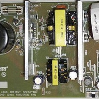
KIT REF DESIGN PFS762HG
Manufacturer
Power Integrations
Series
HiperTFS®r
Specifications of RDK-249
Main Purpose
Reference Design, PC Power Supply
Embedded
No
Utilized Ic / Part
TFS762HG
Primary Attributes
12V 25A, 5V 2.9A Outputs, 300 ~ 385 VDC Input
Output Voltage
5 V
Input / Supply Voltage (max)
385 VDC
Input / Supply Voltage (min)
300 VDC
Duty Cycle (max)
50 %
Mounting Style
Through Hole
Output Current
2.9 A
Output Power
14.5 W
Lead Free Status / RoHS Status
Lead free / RoHS Compliant
Secondary Attributes
-
Other names
596-1398


FILAR_MAIN
RDC_MAIN
AC Resistance Ratio (Main)
CMA_MAIN
J_MAIN
AWG_AUX
OD_MAIN
FILAR_AUX
RDC_AUX
AC Resistance Ratio (Aux)
CMA_AUX
J_AUX
Estimated Power Loss
PCOPPER_MAIN
PCOPPER_AUX
PCORE
PTOTAL
SECONDARY OUTPUT PARAMETERS
ISFWDRMS
ISFWD2RMS
ISCATCHRMS
ISCATCH2RMS
IDAVMAINF
IDAVMAINC
IDAVOUT2F
IDAVOUT2C
IRMSMAIN
IRMSOUT2
VPIVMAINF
VPIVMAINC
VPIVOUT2F
VPIVOUT2C
VPIVB
HiperTFS STANDBY SECTION (FLYBACK STAGE)
ENTER APPLICATION VARIABLES
VACMIN
VACMAX
fL
VO_SB
IO_SB
IO_SB_PK
POUT_SB
POUT_SB_TOTAL
POUT_SB_PK
Power Integrations, Inc.
Tel: +1 408 414 9200 Fax: +1 408 414 9201
www.powerint.com
% Derating
100%
100%
100%
100%
100%
5.00
2.00
2.90
265
85
50
Info
260.5
18.99
21.16
14.18
14.92
10.32
13.6
0.00
0.00
0.00
0.00
0.00
1.98
0.00
45.3
33.4
32.4
14.7
N/A
2.0
4.3
4.0
0.0
2.0
0.0
0.0
0.0
2.7
0.0
2.2
4.9
0.0
0.0
10
A/mm^2
A/mm^2
mohm
mohm
AWG
CMA
CMA
mm
Hz
W
W
W
W
W
W
W
A
A
A
A
A
A
A
A
A
A
V
V
V
V
V
V
V
V
A
Number of parallel strands for main output
Reisstance of wire for main inductor winding
Ratio of total resistance (AC + DC) to the DC
resistance (using Dowell curves)
Cir mils per amp for main inductor winding
Current density in main inductor winding
Aux winding wire gauge
Auxilliary winding wire gauge outer diameter
Number of parallel strands for aux output
Reisstance of wire for aux inductor winding
Ratio of total resistance (AC + DC) to the DC
resistance (using Dowell curves)
!!! Info. Low CMA may cause overheating.
Verify acceptable temperature rise
Current density in auxilliary winding
Copper loss in main inductor windinig
Copper loss in aux inductor winidgs
Total losses in output choke
Max. fwd sec. RMS current (at DVNOM)
Max. fwd sec. RMS current (at DVNOM)
Max. catch sec. RMS current (at DVNOM)
Max. catch sec. RMS current (at DVNOM)
Maximum average current, Main rectifier
(single device rating)
Maximum average current, Main rectifier
(single device rating)
Maximum average current, Main rectifier
(single device rating)
Maximum average current, Main rectifier
(single device rating)
Maximum RMS current, Main output
capacitor
Maximum RMS current, Out2 output
capacitor
Main Forward Diode peak-inverse voltage (at
VDSOP)
Main Catch Diode peak-inverse voltage (at
VOVOFF_MAX)
Output2 Forward Diode peak-inverse voltage
(at VDSOP)
Output2 Catch Diode peak-inverse voltage
(at VOVOFF_MAX)
Bias output rectifier peak-inverse voltage (at
VDSOP)
Minimum AC Input Voltage
Maximum AC Input Voltage
AC Mains Frequency
Output Voltage (at continuous power)
Power Supply Output Current (corresponding
to peak power)
Continuous Output Power
Total Standby power (Includes Bias winding
power)
Peak Standby Output Power
Total core loss
Page 24 of 48
Related parts for RDK-249
Image
Part Number
Description
Manufacturer
Datasheet
Request
R

Part Number:
Description:
KIT REF DESIGN TOP HX FOR TOP258
Manufacturer:
Power Integrations
Datasheet:

Part Number:
Description:
KIT REF DESIGN LINKSWITCH 2
Manufacturer:
Power Integrations
Datasheet:

Part Number:
Description:
KIT REF DESIGN 1.2W PS TN FAMILY
Manufacturer:
Power Integrations
Datasheet:

Part Number:
Description:
KIT REF DESIGN 36-72W MOTOR DRVR
Manufacturer:
Power Integrations
Datasheet:

Part Number:
Description:
KIT REF DESIGN FOR LNK457D
Manufacturer:
Power Integrations
Datasheet:

Part Number:
Description:
REFERENCE DESIGN LINKSWITCH-PH
Manufacturer:
Power Integrations
Datasheet:

Part Number:
Description:
Specifications: Manufacturer: Power Integrations ; Output Voltage: 380 VDC ; Input / Supply Voltage (Max): 264 VAC ; Input / Supply Voltage (Min): 90 VAC ; Mounting Style: Through Hole ; Output Current: 0.913 A ; Output Power: 347 W
Manufacturer:
Power Integrations, Inc.

Part Number:
Description:
Power Management Modules & Development Tools TOPSwitch-JX REF. DESIGN KIT
Manufacturer:
Power Integrations
Datasheet:
Part Number:
Description:
Power Management IC Development Tools REF DESIGN RDR-292 PFF LED STREET LIGHT
Manufacturer:
Power Integrations

Part Number:
Description:
KIT REF DESIGN FOR LNK403EG
Manufacturer:
Power Integrations
Datasheet:

Part Number:
Description:
KIT REF DESIGN FOR LNK406EG
Manufacturer:
Power Integrations
Datasheet:

Part Number:
Description:
KIT REF DESIGN DG CAPZERO
Manufacturer:
Power Integrations
Datasheet:

Part Number:
Description:
KIT REF DESIGN LINKSWITCH-CV
Manufacturer:
Power Integrations
Datasheet:
Part Number:
Description:
Specifications: Family: Eval Boards - DC/DC & AC/DC (Off-Line) SMPS ; Series: HiperLCS™ ; Main Purpose: DC/DC, Step Down ; Outputs and Type: 1, Isolated ; Power - Output: 150W ; Voltage - Output: 24V ; Current - Output: 6.25A ; Voltage - Input:
Manufacturer:
Power Integrations, Inc.
Datasheet:

Part Number:
Description:
KIT REFERENCE DESIGN W/TN376PN
Manufacturer:
Power Integrations
Datasheet: