EVB-USB2412 SMSC, EVB-USB2412 Datasheet - Page 3
EVB-USB2412
Manufacturer Part Number
EVB-USB2412
Description
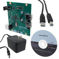
EVALUATION BOARD FOR USB2412
Manufacturer
SMSC
Specifications of EVB-USB2412
Design Resources
EVB-USB2412 Schematic EVB-USB2412 BOM
Main Purpose
Interface, USB 2.0 Hub
Embedded
No
Utilized Ic / Part
USB2421
Primary Attributes
Dual Port Hub, High Speed (480Mbps)
Secondary Attributes
Single 5V Supply
Lead Free Status / RoHS Status
Lead free / RoHS Compliant
Other names
638-1106


EVB-USB2412 Evaluation Board User Manual
2
SMSC EVB-USB2412
2.1
2.1.1
2.1.2
2.1.3
2.1.4
Hardware Configuration
Hardware Description
Downstream Ports
Powered State LED
Port Power LEDs
Connector Description
CONNECTOR
The EVB-USB2412 has one onboard regulator, which generates +3.3 VDC from a +5.0 VDC power
supply. An alternate footprint (U7) was added to support industrial temperature range operation. The
alternate footprint supports a larger package and has ties into the ground plane for better thermal
dissipation. The USB2412 generates is own PLL and core power rails with individual on chip
regulators. No external regulators are needed to support these functions.
The USB2412 Hub consumes power from the +3.3 VDC supply while the MIC2026 Power distribution
switch consumes power from the +5.0 VDC supply. The MIC2026 Power distribution switch supplies
downstream power to each attached device.
Downstream ports are numbered 1 and 2 with individual port power controllers. The port power
controllers provide 5 Volt power with over-current protection to the downstream devices. Upstream and
downstream port connectors have USB 2.0 compliant decoupling, a separate shield ground, and
optional filtering for EMI on signal ground and power. Additional ESD protection for USB signals is
provided by optional diode bridges and common mode chokes. This gives protection up to 25 kV direct
contact to USB signals.
Optionally, the down stream ports can be strapped to report as removable by changing the resistors
installed that configure NON_REM0 and NON_REM1. See the schematic on the CD-ROM included
with your EVB-USB2412 for implementation details.
An optional LED (LED3) indicates when +5.0 VDC power is present.
LED1 and LED2 indicate when port power is available to the associated downstream USB port.
The EVB-USB2412 has a set of standard USB style connectors, one of type B for the upstream port
and two of type A for downstream ports. Power is supplied via a 2.1 mm power jack.
of the connectors. For more details on the pinout of these connectors, please see the EVB-USB2412
schematics on the CD-ROM included with your EVB-USB2412.
J1
J2
J3
J4
Table 2.1 Connector Description
Power Jack 2.1 mm
USER MANUAL
USB A
USB A
USB B
TYPE
3
Downstream USB Port 1
Downstream USB Port 2
+5.0 VDC Power Supply
Upstream USB Port 0
DESCRIPTION
Revision 0.2 (02-02-10)
Table 2.1
lists all
Related parts for EVB-USB2412
Image
Part Number
Description
Manufacturer
Datasheet
Request
R

Part Number:
Description:
BOARD EVAL FOR USB2514 48-QFN
Manufacturer:
SMSC
Datasheet:

Part Number:
Description:
Networking Modules & Development Tools LAN7500 USB 2.0 BRD 10/100/1000 GigB
Manufacturer:
SMSC
Datasheet:

Part Number:
Description:
BOARD EVAL FOR USB2514/USB2514I
Manufacturer:
SMSC
Datasheet:

Part Number:
Description:
BOARD EVAL FOR USB2512/USB2512I
Manufacturer:
SMSC
Datasheet:

Part Number:
Description:
BOARD EVAL FOR USB2513/USB2513I
Manufacturer:
SMSC
Datasheet:

Part Number:
Description:
BOARD EVALUATION FOR EMC1043
Manufacturer:
SMSC
Datasheet:
Part Number:
Description:
EVALUATION BOARD FOR USB3311C
Manufacturer:
SMSC
Datasheet:
Part Number:
Description:
EVALUATION BOARD FOR USB3317C
Manufacturer:
SMSC
Datasheet:

Part Number:
Description:
EVALUATION BOARD USB2241-AEZG
Manufacturer:
SMSC
Datasheet:

Part Number:
Description:
BOARD EVAL USB2524 SHARE/SWITCH
Manufacturer:
SMSC
Datasheet:

Part Number:
Description:
BOARD EVALUATION FOR USB2502
Manufacturer:
SMSC
Datasheet:
Part Number:
Description:
BOARD EVALUATION FOR USB2504
Manufacturer:
SMSC
Datasheet:

Part Number:
Description:
EVALUATION BOARD LAN9500-ABZJ
Manufacturer:
SMSC
Datasheet:
Part Number:
Description:
Ethernet Modules & Development Tools LAN9500 Design Kit Low-Cost USB Dongle
Manufacturer:
SMSC
Datasheet: