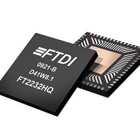
FT2232HQ-REEL FTDI, FT2232HQ-REEL Datasheet - Page 18

FT2232HQ-REEL
Manufacturer Part Number
FT2232HQ-REEL
Description
USB Interface IC USB HS to Dual UART/ FIFO/SPI/JTAG/I2C
Manufacturer
FTDI
Datasheet
1.FT2232HQ_-_REEL.pdf
(63 pages)
Specifications of FT2232HQ-REEL
Mounting Style
SMD/SMT
Package / Case
QFN
Lead Free Status / RoHS Status
Lead free / RoHS Compliant
Available stocks
Company
Part Number
Manufacturer
Quantity
Price
Company:
Part Number:
FT2232HQ-REEL
Manufacturer:
INFINEON
Quantity:
872
3.4.8 FT2232H Pins Configured as a Host Bus Emulation Interface
The FT2232H can be used to combine channel A and channel B to be configured as a host bus emulation
interface mode which emulates a standard 8048 or 8051 MCU host.
When configured in this mode, the pins used and the descriptions of the signals are shown in Table 3.11
Table 3.11 Channel A and Channel B Host Bus Emulation Interface Configured Pin Descriptions
For a functional description of this mode, please refer to section 4.7 MCU Host Bus Emulation Mode
24,23,22,21,
34,33,32,30,
19,18,17,16
29,28,27,26
Pin No.
38
39
40
41
43
44
45
46
Copyright © 2010 Future Technology Devices International Limited
ADBUS[7:0]
CLKOUT
A[15:8]
IORDY
Name
WR#
RD#
I/O0
I/O1
CS#
ALE
FT2232H DUAL HIGH SPEED USB TO MULTIPURPOSE UART/FIFO IC
I/O
I/O
OUTPUT
OUTPUT
OUTPUT
OUTPUT
OUTPUT
OUTPUT
INPUT
Type
I/O
Master clock. Outputs the clock signal being used by the
configured interface.
MPSSE mode instructions to set / clear or read the high
byte of data can be used with this pin. Please refer to
Application Note AN_108 for operation of these
instructions.
MPSSE mode instructions to set / clear or read the high
byte of data can be used with this pin. In addition this
pin has instructions which will make the controller wait
until it is high, or wait until it is low. This can be used to
connect to an IRQ pin of a peripheral chip. The FT2232H
will wait for the interrupt, and then read the device, and
pass the answer back to the host PC. I/O1 must be held
in input mode if this option is used. Please refer to
Application Note AN_108 for operation of these
instructions.
Active low write output. (Data is setup before WR# goes
Multiplexed bidirectional Address/Data bus AD7 to AD0
operation if driven low. Pull up to VCORE if not being
Fast Serial Interface Configuration Description
Extends the time taken to perform a Read or Write
Active low chip select device during Read or Write.
low, and is held after WR# goes high)
Positive pulse to latch the address
Extended Address A15 to A8
Active low read output.
Document No.: FT_000061
used.
Clearance No.: FTDI#77
Datasheet Version 2.10
18


