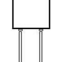
HT13CB103JN Kemet, HT13CB103JN Datasheet - Page 50

HT13CB103JN
Manufacturer Part Number
HT13CB103JN
Description
Multilayer Ceramic Capacitors (MLCC) - Leaded HT13 0.01uF 100volts X7R 5%
Manufacturer
Kemet
Series
HTr
Datasheet
1.HT13CN471KN.pdf
(53 pages)
Specifications of HT13CB103JN
Voltage Rating
100 Volts
Termination Style
Axial
Operating Temperature Range
- 55 C to + 200 C
Product
High Temperature MLCCs
Dimensions
3.43 mm Dia. x 6.6 mm L
Capacitance
0.01 uF
Tolerance
5 %
Temperature Coefficient
X7R
Lead Free Status / RoHS Status
Lead free / RoHS Compliant
Higher-voltage parts may require further encapsulation to prevent surface breakdown. Parts should be cleaned and oven dried
at 85°C before further encapsulation. Silicone rubbers or an epoxy may be used. De-airing of encapsulants is recommended.
We recommend that a heat sink be attached to the lead between the soldering iron and the capacitor during installation sol-
dering. Testing of higher-voltage parts before encapsulation may be done in a suitable dielectric fluid such as Freon.
Disc ceramic capacitors made under strict quality control proce-
dures are a reliable component. Special attention is given to the
ceramic pressing operation to assure high and uniform ceramic
density.
These parts are manufactured for the quality conscious customer.
Parts are available screened to MIL-PRF-49467 established relia-
bility specification.
Style
D50, etc.
Dielectric
N = C0G (NP0)
W = X7R
Y = X5U
Voltage
30 =3000V
100 =10,000V
etc.
Dissipation Factor
Temperature Coefficient
Voltage Coefficient
Dielectric Withstanding
Voltage Test
Insulation Resistance
(25ºC)
Operating Temperature
Range (rated voltage)
Thickness:
Inches (mm) max.
CERAMIC TYPE
(D30)
301M
3kV
KEC
Date Code
© KEMET Electronics Corporation • PO Box 5928 • Greenville, SC 29606 • www.kemet.com
30
FEATURES
MARKING
D50
PART NUMBER AND ORDERING INFORMATION
7.5kV = 0.28 (7.11)
(All Other Sizes)
D50W122M
3kV
KEC
Date Code
10kV = 0.35 (8.89)
15kV = 0.45 (11.43)
20kV = 0.55 (13.97)
30kV = 0.95 (24.13)
40kV = 1.20 (30.48)
50kV = 1.50 (38.10)
3kV = 0.15 (3.81)
5kV = 0.20 (5.08)
20 to 50kV at rated +10kV
3 to 15kV at 1.5x rated,
Disc Ceramic Capacitor
100k megohms or
whichever is less
1k megohms-μF,
-55ºC to +125ºC
C0G (NP0)
±30ppm/ºC
W
DIELECTRIC COMPARISON
0.1%
0
High Voltage
INSTALLATION
D Series
122
Lead Type: Solder plated, copper-clad steel (CCFE)-
20 to 50kV at rated +10kV
3 to 15kV at 1.5x rated,
100k megohms or
whichever is less
1k megohms-μF,
-55ºC to +125ºC
M
D30, D40: 0.025” (22GA)
D50 & Larger: 0.032” (20GA)
±15%
2.5%
-20%
X7R
M
CAPACITOR OUTLINE DRAWING
Q
20 to 50kV at rated +10kV
3 to 15kV at 1.5x rated,
100 megohms-μF,
whichever is less
10k megohms or
-55ºC to +85ºC
+22% -56%
2.5%
X5U
N/A
No Leads
Add to part number if required
Group A Screening*
Add to part number if required
*MIL-PRF-49467 (subgroup 1)
except Corona
Capacitance Value
First two digits are significant,
last digit is number of zeroes,
i.e., 472=4700pF
Tolerance
J = ±5% C0G (NP0)
K = ±10%
M = ±20%
P = 0/+100%
Z = -20%/+80%
49


