GQM1885C2A2R7BB01D Murata, GQM1885C2A2R7BB01D Datasheet - Page 27
GQM1885C2A2R7BB01D
Manufacturer Part Number
GQM1885C2A2R7BB01D
Description
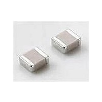
Multilayer Ceramic Capacitors (MLCC) - SMD/SMT 0603 2.7pF 100volts C0G +/-0.1pF
Manufacturer
Murata
Series
GQMr
Datasheet
1.GQM1885C2A3R9BB01D.pdf
(30 pages)
Specifications of GQM1885C2A2R7BB01D
Voltage Rating
100 Volts
Operating Temperature Range
- 55 C to + 125 C
Temperature Coefficient / Code
C0G (NP0)
Product
Low ESR MLCCs
Dimensions
0.8 mm W x 1.6 mm L x 0.8 mm H
Termination Style
SMD/SMT
Capacitance
2.7 pF
Tolerance
0.1 pF
Package / Case
0603 (1608 metric)
Capacitance Tolerance
± 0.1pF
Capacitor Dielectric Type
Ceramic Multi-Layer
Capacitor Case Style
0603
No. Of Pins
2
Lead Spacing
0.5mm
Operating Temperature
RoHS Compliant
Svhc
No SVHC (15-Dec-2010)
Rohs Compliant
Yes
Lead Free Status / RoHS Status
Lead free / RoHS Compliant
Available stocks
Company
Part Number
Manufacturer
Quantity
Price
Company:

Part Number:
GQM1885C2A2R7BB01D
Manufacturer:
MURATA
Quantity:
640 000


46 – Innovator in Electronics
Application Specific Capacitors
High Frequency Ceramic Capacitors – GQM Series
GQM Soldering and Mounting
7. Washing
6. Correction with a Soldering Iron
FAILURE TO FOLLOW THE ABOVE CAUTIONS MAY
RESULT, WORST CASE, IN A SHORT CIRCUIT AND
FUMING WHEN THE PRODUCT IS USED.
When sudden heat is applied to the components when using a soldering iron, the mechanical strength of
the components will decrease because the extreme temperature change can cause deformations inside the
components. In order to prevent mechanical damage to the components, preheating is required for both
the components and the PCB board. Preheating conditions (the "Temperature of the Soldering Iron tip",
"Preheating Temperature", "Temperature Differential" between the iron tip and the components and the
PCB) should be within the conditions of Table 3. It is required to keep the temperature differential
between the soldering Iron and the component surfaces (ΔT) as small as possible.
After soldering, do not allow the component/PCB to rapidly cool down.
The operating time for the re-working should be as short as possible. When re-working time is too long,
Optimum Solder amount when re-working with a Soldering lron
solder fillet should be lower than 2/3's of the thickness of the
component or 0.5mm whichever is smaller. In case of 0805
and larger sizes (GQM21/22), the top of the solder fillet
should be lower than 2/3's of the thickness of the component.
If the solder amount is excessive, the risk of cracking is higher
during board bending or under any other stressful condition.
A Soldering iron with a tip of ø3mm or smaller should be used.
It is also necessary to keep the soldering iron from touching
the components during the re-work.
Solder wire with ø0.5mm or smaller is required for soldering.
Excessive output of ultrasonic oscillation during cleaning
causes PCBs to resonate, resulting in cracked chips or
broken solder. Take note not to vibrate PCBs.
In case of sizes smaller than 0603, (GQM18), the top of the
Table 3
GQM18/21
G
*Applicable for both Pb-Sn and Lead Free Solder. Pb-Sn Solder: Sn-37Pb
it may cause solder leaching, and that will cause a reduction in the adhesive strength of the terminations.
Q
M
2
2
Part Number
Temperature
of Soldering
350
2
8
Iron tip
0
max.
max.
w
w
Temperature
150
150
Lead Free Solder: Sn-3.0Ag-0.5Cu
Preheating
w
w
w
w
min.
min.
w
w
w
.
.
Temperature
ΔT 190
ΔT 130
Differential
m
m
.
(ΔT)
m
u
u
u
r
r
Atmosphere
r
a
a
Air
Air
a
t
t
a
a
t
a
.
.
c
c
.
c
o
o
o
m
m
m
Solder amount
in section.
C-29-C
Related parts for GQM1885C2A2R7BB01D
Image
Part Number
Description
Manufacturer
Datasheet
Request
R

Part Number:
Description:
Murata Microblower 20x20 DCDC Driver Board - Samples Only
Manufacturer:
Murata
Part Number:
Description:
357-036-542-201 CARDEDGE 36POS DL .156 BLK LOPRO
Manufacturer:
Murata
Datasheet:
Part Number:
Description:
Manufacturer:
Murata
Datasheet:
Part Number:
Description:
Manufacturer:
Murata
Datasheet:
Part Number:
Description:
Manufacturer:
Murata
Datasheet:
Part Number:
Description:
Manufacturer:
Murata
Datasheet:
Part Number:
Description:
Manufacturer:
Murata
Datasheet:
Part Number:
Description:
Manufacturer:
Murata
Datasheet:
Part Number:
Description:
Manufacturer:
Murata
Datasheet:
Part Number:
Description:
BLM21BD751SN1On-Board Type (DC) EMI Suppression Filters
Manufacturer:
Murata
Datasheet:
Part Number:
Description:
BLM15AG100SN1On-Board Type (DC) EMI Suppression Filters
Manufacturer:
Murata
Datasheet:
Part Number:
Description:
NFE31PT222Z1E9On-Board Type (DC) EMI Suppression Filters
Manufacturer:
Murata
Datasheet:
Part Number:
Description:
Chip Coil
Manufacturer:
Murata
Datasheet:
Part Number:
Description:
Chip Coil
Manufacturer:
Murata
Datasheet: