C3225Y5V1A226Z TDK Corporation, C3225Y5V1A226Z Datasheet - Page 10
C3225Y5V1A226Z
Manufacturer Part Number
C3225Y5V1A226Z
Description
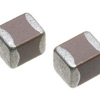
Multilayer Ceramic Capacitors (MLCC) - SMD/SMT 1210 22uF 10volts Y5V +80-20%
Manufacturer
TDK Corporation
Series
Cr
Datasheet
1.C0603C0G1E120J.pdf
(31 pages)
Specifications of C3225Y5V1A226Z
Voltage Rating
10 Volts
Operating Temperature Range
- 30 C to + 85 C
Temperature Coefficient / Code
Y5V
Product
Low ESR MLCCs
Dimensions
2.5 mm W x 3.2 mm L x 1.15 mm H
Termination Style
SMD/SMT
Capacitance
22 uF
Tolerance
- 20 %, 80 %
Package / Case
1210 (3225 metric)
Lead Free Status / RoHS Status
Lead free / RoHS Compliant
Available stocks
Company
Part Number
Manufacturer
Quantity
Price
Company:

Part Number:
C3225Y5V1A226ZT000A
Manufacturer:
TDK
Quantity:
357


C Series C1608 (EIA CC0603) Types
FEATURES
• High capacitance has been achieved through precision
• A monolithic structure ensures superior mechanical strength and
• High-accuracy automatic mounting is facilitated through the
• Composed of only ceramics and metals, these capacitors
• Low stray capacitance ensures high conformity with nominal
• Low residual inductance assures superior frequency
• Because electrostatic capacity has been obtained up to the
• Owing to their low ESR and excellent frequency characteristics,
SHAPES AND DIMENSIONS
• Conformity to RoHS Directive: This means that, in conformity with EU Directive 2002/95/EC, lead, cadmium, mercury, hexavalent chromium, and specific
• All specifications are subject to change without notice.
Please read the precautions before using this catalog.
bromine-based flame retardants, PBB and PBDE, have not been used, except for exempted applications.
technologies that enable the use of multiple thinner ceramic
dielectric layers.
reliability.
maintenance of very precise dimensional tolerances.
provide extremely dependable performance, exhibiting virtually
no degradation even when subjected to temperature extremes.
values, thereby simplifying the circuit design process.
characteristics.
electrolytic capacitor range, these capacitors offer long service
life and are optimally suited for power supply designs that
require high levels of reliability.
these products are optimally suited for high frequency and high-
density type power supplies.
1.6±0.1
0.2min.
Dimensions in mm
PRODUCT IDENTIFICATION
(1) Series name
(2) Dimensions L×W
1608
(3) Capacitance temperature characteristics
Class 1 (Temperature compensation)
Temperature
characteristics
CH
C0G
Class 2 (Temperature stable and general purpose)
Temperature
characteristics
JB
JF
X7R
X5R
Y5V
X6S
(4) Rated voltage Edc
0G
0J
1A
1C
1E
1H
(5) Nominal capacitance
The capacitance is expressed in three digit codes and in units of
pico farads (pF).
The first and second digits identify the first and second significant
figures of the capacitance.
The third digit identifies the multiplier.
R designates a decimal point.
010
100
102
0R5
(6) Capacitance tolerance
Symbol
C
D
J
K
M
Z
(7) Packaging style
T
B
(1) (2) (3) (4) (5) (6) (7)
C 1608 CH 1H 100 D
1.6×0.8mm
Capacitance change
0±60ppm/°C
0±30ppm/°C
Capacitance change
±10%
+30, –80%
±15%
±15%
+22, –82%
±22%
4V
6.3V
10V
16V
25V
50V
1pF
10pF
1,000pF
0.5pF
Tolerance
±0.25pF
±0.5pF
±5%
±10%
±20%
+80, –20%
Taping (reel)
Bulk
Conformity to RoHS Directive
006-03 / 20100409 / e412_c.fm
Temperature range
–25 to +85°C
–55 to +125°C
Temperature range
–25 to +85°C
–25 to +85°C
–55 to +125°C
–55 to +105°C
–55 to +85°C
–30 to +85°C
Applicable capacitance
range
10pF or less
Over 10pF
(9/30)
Related parts for C3225Y5V1A226Z
Image
Part Number
Description
Manufacturer
Datasheet
Request
R

Part Number:
Description:
TDK DC to DC Converters, DC to AC Inverters
Manufacturer:
TDK Corporation
Datasheet:
Part Number:
Description:
TDK DC to DC Converters, DC to AC Inverters
Manufacturer:
TDK Corporation
Datasheet: