ADXL311JE-REEL Analog Devices Inc, ADXL311JE-REEL Datasheet - Page 8
ADXL311JE-REEL
Manufacturer Part Number
ADXL311JE-REEL
Description
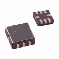
IC ACCELER DUAL-AX 2.0G 8PLCC
Manufacturer
Analog Devices Inc
Series
iMEMS®r
Datasheet
1.ADXL311EB.pdf
(12 pages)
Specifications of ADXL311JE-REEL
Axis
X, Y
Acceleration Range
±2g
Sensitivity
174mV/g
Voltage - Supply
2.4 V ~ 5.25 V
Output Type
Analog
Bandwidth
10Hz ~ 500Hz Selectable
Mounting Type
Surface Mount
Package / Case
8-CLCC
Lead Free Status / RoHS Status
Lead free / RoHS Compliant
Interface
-
Available stocks
Company
Part Number
Manufacturer
Quantity
Price
Company:

Part Number:
ADXL311JE-REEL
Manufacturer:
CAN
Quantity:
8 099
Part Number:
ADXL311JE-REEL
Manufacturer:
ADI/亚德诺
Quantity:
20 000


ADXL311
THEORY OF OPERATION
The ADXL311 is a complete, dual-axis acceleration measurement
system on a single monolithic IC. It contains a polysilicon, surface-
micromachined sensor and signal conditioning circuitry to
implement an open-loop acceleration measurement architecture.
The output signals are analog voltage proportional to acceleration.
The ADXL311 is capable of measuring both positive and negative
accelerations to at least ±2 g. The accelerometer can measure
static acceleration forces, such as gravity, allowing it to be used
as a tilt sensor.
The sensor is a polysilicon, surface-micromachined structure
built on top of the silicon wafer. Polysilicon springs suspend the
structure over the surface of the wafer and provide a resistance
against acceleration forces. Deflection of the structure is measured
using a differential capacitor that consists of independent fixed
plates and central plates attached to the moving mass. The fixed
plates are driven by 180° out-of-phase square waves. Acceleration
deflects the beam and unbalances the differential capacitor,
resulting in an output square wave whose amplitude is propor-
tional to acceleration. Phase-sensitive demodulation techniques
are then used to rectify the signal and determine the direction
of the acceleration.
The output of the demodulator is amplified and brought off chip
through a 32 kΩ resistor. At this point, the user can set the signal
bandwidth of the device by adding a capacitor. This filtering
improves measurement resolution and helps prevent aliasing.
APPLICATIONS
Power Supply Decoupling
For most applications, a single 0.1 µF capacitor, CDC, adequately
decouples the accelerometer from noise on the power supply.
However, in some cases, particularly where noise is present at
the 140 kHz internal clock frequency (or any harmonic thereof),
noise on the supply can cause interference on the ADXL311
output. If additional decoupling is needed, a 100 Ω (or smaller)
resistor or ferrite beads can be inserted in the supply line of the
ADXL311. Additionally, a larger bulk bypass capacitor (in the
1 µF to 4.7 µF range) can be added in parallel to CDC.
Rev. B | Page 8 of 12
Setting the Bandwidth Using C
The ADXL311 has provisions for band limiting the X
Y
low-pass filtering for antialiasing and noise reduction. The
equation for the −3 dB bandwidth is
or, more simply,
The tolerance of the internal resistor (R
as much as ±15% of its nominal value of 32 kΩ, and the band-
width varies accordingly. A minimum capacitance of 1000 pF
for C
Table 5. Filter Capacitor Selection, C
Bandwidth
10 Hz
50 Hz
100 Hz
200 Hz
500 Hz
SELF TEST
The ST pin controls the self-test feature. When this pin is set to
V
ometer. The resulting movement of the beam allows the user to
test if the accelerometer is functional. The typical change in output
is 290 mg (corresponding to 50 mV). This pin can be left open
circuit or connected to common in normal use.
DESIGN TRADE-OFFS FOR SELECTING FILTER
CHARACTERISTICS: THE NOISE/BW TRADE-OFF
The accelerometer bandwidth selected ultimately determines
the measurement resolution (smallest detectable acceleration).
Filtering can lower the noise floor, which improves the resolution
of the accelerometer. Resolution is dependent on the analog filter
bandwidth at X
OUT
DD
, an electrostatic force is exerted on the beam of the acceler-
pins. Capacitors must be added at these pins to implement
X
and C
F
F
3 –
3 –
Y
dB
dB
is required in all cases.
OUT
=
=
/ 1
5
and Y
µ
(
π 2
/ F
(
C
32
OUT
(
X,Y
kΩ
Capacitor (µF)
0.47
0.10
0.05
0.027
0.01
.
)
)
×
C
X
(
X
and C
,
Y
)
X
)
FILT
and C
Y
) can vary, typically
Y
OUT
and
Related parts for ADXL311JE-REEL
Image
Part Number
Description
Manufacturer
Datasheet
Request
R

Part Number:
Description:
IC ACCELEROMETER COMPACT 8-CLCC
Manufacturer:
Analog Devices Inc
Datasheet:

Part Number:
Description:
±1.7g Dual-Axis IMEMS Accelerometer Evaluation Board
Manufacturer:
Analog Devices Inc
Datasheet:

Part Number:
Description:
Inertial Sensor Evaluation System
Manufacturer:
Analog Devices Inc
Datasheet:
Part Number:
Description:
Manufacturer:
Analog Devices Inc
Datasheet:
Part Number:
Description:
Manufacturer:
Analog Devices Inc
Datasheet:
Part Number:
Description:
Manufacturer:
Analog Devices Inc
Datasheet:
Part Number:
Description:
Manufacturer:
Analog Devices Inc
Datasheet:
Part Number:
Description:
Manufacturer:
Analog Devices Inc
Datasheet:
Part Number:
Description:
Manufacturer:
Analog Devices Inc
Datasheet:
Part Number:
Description:
Manufacturer:
Analog Devices Inc
Datasheet:
Part Number:
Description:
Manufacturer:
Analog Devices Inc
Datasheet:
Part Number:
Description:
Manufacturer:
Analog Devices Inc
Datasheet:
Part Number:
Description:
Manufacturer:
Analog Devices Inc
Datasheet: