70.320.1628.0 WIELAND ELECTRIC, 70.320.1628.0 Datasheet - Page 594
70.320.1628.0
Manufacturer Part Number
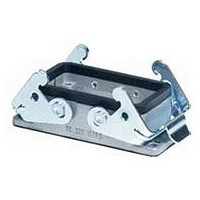
70.320.1628.0
Description
Connector Housing
Manufacturer
WIELAND ELECTRIC
Series
Revos FLEXr
Datasheet
1.07.311.0155.0.pdf
(900 pages)
Specifications of 70.320.1628.0
Connector Shell Size
16
Connector Body Material
Aluminum Alloy
Connector Mounting
Cable
No. Of Contacts
16
Accessory Type
Open Bottom Housing
For Use With
Industrial Multipole Connectors
Lead Free Status / RoHS Status
Lead free / RoHS Compliant


WEG
WEG
System benefits
• closed housing available in four different sizes
• parallel connection of the modules in various lengths
• compact housing made from high quality material
• UL 94-V-0 polyamide 66/6
UL-Data
CSA-Data
Approvals
Dimensions (mm): W x H x D
592
Electronic empty housings
possible via the latchable U-foot
Empty housing, complete with U-Foot, without PCB
Housing dimensions, PCB dimensions
Technical data
Rated cross-section
Wire range single core
Wire range finely stranded
Rated voltage
Rated current
Type of protection
Insulation strip length
Regulations, norms
Accessories
Mounting rail 35, DIN rail 7.5 mm high
Mounting rail 35, DIN rail 15 mm high
Mounting rail 32, G-rail
PCB (see drawing for dimensions) (hole grid)
End clamp, Polyamide
End clamp, Polyamide
Marker tag, unmarked
Marker tag, marked
See pages 582–585 for further labelling systems
Description
n
10 mm wide U-Foot
8 mm wide TS 35
L = 2 m
L = 2 m
L = 2 m
No. 22–10 AWG/600 V
No. 20–10 AWG
L
20 x 60.6 x 63
See page 602
4 mm
0.14–6 mm
0.14–4 mm
400 V/4 kV/3
max. 10 A
IP 20
7 mm
DIN VDE 0611
EN 60947-7-1: 1991/DIN VDE 0611 T1/08.92
35 x 27 x 7,5 EN 60715 98.300.0000.0
35 x 24 x 15 EN 60715 98.360.0000.0
9006 EN 60715 G-32
9708/2 S 35
WE 1/U
9003 C
9003 CB
2
2
2
(EN 60 947-7-1 / DIN VDE 0611 T1)
(EN 60 947-7-1 / DIN VDE 0611 T1)
Part 1
(11.77)
Part No.
57.801.0053.0
98.190.0000.0
Z8.000.0123.1
Z5.522.8553.0
Z5.523.5753.0
04.242.0651.0
04.842.0651.0
Box Qty
100
100
500
500
10
10
1
1
1
No. 22–10 AWG/600 V
No. 20–10 AWG
L
16.5 x 60.6 x 90.5
See page 602
4 mm
0.14–6 mm
0.14–4 mm
400 V/4 kV/3
max. 10 A
IP 20
I
7 mm
DIN VDE 0611
EN 60947-7-1: 1991/DIN VDE 0611 T1/08.92
35 x 27 x 7,5 EN 60715 98.300.0000.0
35 x 24 x 15 EN 60715 98.360.0000.0
9006 EN 60715 G-32
9708/2 S 35
WE 1/U
9003 C
9003 CB
2
2
2
(EN 60 947-7-1 / DIN VDE 0611 T1)
(EN 60 947-7-1 / DIN VDE 0611 T1)
Part 1
(11.77)
57.801.5053.0
98.190.0000.0
Z5.522.8553.0
Z5.523.5753.0
04.241.0651.0
04.841.0651.0
Subject to change without further notice
100
100
500
500
10
1
1
1
Related parts for 70.320.1628.0
Image
Part Number
Description
Manufacturer
Datasheet
Request
R


Part Number:
Description:
End Plate
Manufacturer:
WIELAND ELECTRIC
Datasheet:

Part Number:
Description:
END PLATE, WK SERIES TERMINAL BLOCK
Manufacturer:
WIELAND ELECTRIC
Datasheet:
Part Number:
Description:
END PLATE, WK/WKN SERIES TERMINAL BLOCK
Manufacturer:
WIELAND ELECTRIC
Datasheet:

Part Number:
Description:
PARTITION PLATE WK SERIES TERMINAL BLOCK
Manufacturer:
WIELAND ELECTRIC
Datasheet: