C146-10G024-500-1 Amphenol-Tuchel Electronics, C146-10G024-500-1 Datasheet - Page 207
C146-10G024-500-1
Manufacturer Part Number
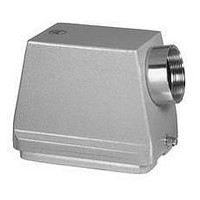
C146-10G024-500-1
Description
SIDE ENTRY HOOD, ALUMINUM ALLOY
Manufacturer
Amphenol-Tuchel Electronics
Specifications of C146-10G024-500-1
Cable Exit Angle
90°
Connector Body Material
Aluminum Alloy
Enclosure Material
Aluminum Alloy
Thread Size - Imperial
PG 21
Accessory Type
Side Entry Hood
Finish
Powder Coating
Material, Housing
Aluminum Die Cast Alloy
Mechanical Life
500 Cycles (Min.)
Temperature, Operating
-40 to +100 °C
For Use With
C146 Rectangular Connectors
Lead Free Status / RoHS Status
Lead free / RoHS Compliant


Amphenol
American Wire Gauge (AWG)
System of numerical designations for wire sizes, based on specified ranges of cross-sectional areas.
Starts with 4/0 (000) at the largest size, going to 3/0, 2/0, 1/0, 1, 2, and up to 40 and beyond for the
smallest size. A step of one AWG number corresponds to a reduction of cross-sectional area of appr. 20 %.
Attenuation
A reduction of power. Occurs naturally when waves travel through lines, wave guides, or media such as air
or water. Is produced additionally by imperfections in electrical or optical connections (attenuation in fibre
optics), e. g. contact resistance, mismatch, etc.
Bulkhead connector
Connector designed to be inserted into a panel cutout from the rear of the panel, thus forming part of the
barrier between two spaces. Back-mounted.
Clearance
The shortest distance in air between two conductive parts, see IEC 60664.
Climatic stability
General term describing the behavior of components under various climatic conditions, e. g. high and low
temperatures, tropical climate, high humidity, moist heat, fungus, atmospheric conditions (industial
atmosphere), reduced air pressure, etc. Climatic conditions for test purposes are explained in IEC 60068,
DIN 46 040.
Connector
A component which terminates conductors for the purpose of providing connection and disconnection to
a suitable mating component which shall not be engaged or disengaged when live. Depending on the
fastening to a cabinet, panel, rack etc. or a cable, they are classified as fixed or free connectors. A
connector comprises one or more contacts and a housing which may have a separate connector insert and
a separate outer housing or shell.
Connector housing
The part of a connector into which the insert and the contacts are assembled. It may function as part of the
locking mechanism.
Connector insert
An insulating element designed to support and position contacts in a connector housing.
Connector life
The number of mating cycles prior to abrasion of the conductive contact surface and which does not result
in a significant rise of the contact resistance. Tests according to test 9a of ICE 60512-5 / DIN EN 60512
Part 5.
Contact
The conductive element in a connector which mates with a corresponding element to provide an electrical
path.
Contact resistance
The electrical resistance of a mated set of contacts under specified conditions. Tested according to tests 2a,
2b, 2c, of IEC 60 512 -2/ DIN EN 60 512-2.
Contact size
The designation used to differentiate one contact from another. It may be denoted by one of the following
numbering systems:
– numbering system: assigned numbers used to denote the size of the contact and its related conductor
accomodation (e. g. in AWG units),
– current rating system: the related current-carrying capacity is used to denote the size of the contact,
– cross-sectional area system: reference is made to the cross-sectional area of the maximum conductor
accommodation to denote the size of the contact, e. g. in mm
Creepage distance
The shortest distance along the surface of the insulating material between two conductive parts. The longer
the distance, the less the risk of arc damage or tracking. Minimum creepage distances are specified
according to the rated voltage and the applicable pollution degree and Comperative Tracking Index.
Crimped connection
A solderless connection made by crimping. IEC 60352-2 / DIN IEC 60352 Part 2.
Crimping die
That part of a crimping tool which forms the crimp(s) and usually incorporates the crimp anvil(s) and the
crimp indentor(s).
Derating curve
The method for determining derating is specified in IEC 60 512-3. Here the combination of ambient
temperature (Tu) and the current (J) leading to the same maximum allowable temperature (Tb) at the
hottest point of the connector are plotted.
DIN
Deutsches Institut für Normung. A German standards organization.
C 146
Connector glossary
2
.
Electromagnetic interference (EMI)
General term describing the undesirable effects of the immission or emission of radio frequency fields.
In connectors electromagnetic interference is prevented by shielding. Shielded connectors normally
provide means to connect the screens of attached cables.
Funnel entry (restricted entry C146 D series)
Flared or widened entrance to a conductor barrel permitting easier insertion of the conductor.
Insertion or withdrawal force
The force required to fully insert or withdraw a set of mated connectors without the effect of coupling,
locking or similar devices. The insertion force is usually greater than the withdrawal force.
Insulation grip
The area of a crimp contact that has been reshaped around the insulation of the conductor by compression
during the crimping operation.
Insulation resistance
The resistance of the insulation between two conductive elements, in particular, the resistance between two
contacts or between a contact and a metallic housing or shield. Tested according to test 3a of IEC 60512-2 /
DIN IEC 60512 Part 2.
Intermateable
Two connectors are intermateable when they are capable of being connected electrically and mechanically
but without regard to their performance and intermountability.
Locator
In a crimping tool the device used for positioning a crimp contact or terminal end.
Locking lever
A mechanical locking device operated by actuating a lever, designed to hold two mated connectors
together. Typically the lever can only be fully locked if the two connectors are correctly mated.
Mating cycle
One mating cycle comprises one insertion and one withdrawal operation. Term used in the definition of
connector life.
Material group
Classification of insulation materials according to their CTI values (CTI = Comperative Tracking Index)
Overvoltage category
A numeral defining a transient overvoltage condition. Overvoltage categories I, II, III and IV are used.
Connector with braking capacity (CBC)
A component which may be engaged or disengaged in normal use, when live or under load. Note: In the
sense of this document the term - live- is used if contacts are under voltage not necessarily with a current
flowing across the contacts. The term - load - is used if a current is flowing across the contacts.
Rated current
A current value assigned by the manufacturer which the connector or PSD can carry continuously (without
interruption) and simultaneously through all its contacts wired with the largest conductor preferrably at an
ambient temperature of 40 °C without the upper temperature being exceeded.
Shield, shielding
Shielding of internal or external electric fields by means of a plane with a uniform electric potential, formed
by metal shells or metallic layers on the inside or outside of plastic shells. The shield is normally
connected to the shielding braid of the cable and/or chassis ground.
Terminal block
An assembly of terminals in a housing or body of insulating material to facilitate interconnection between
multiple conductors. Also called terminal strip or barrier blocks if the terminals are separated by an
insulation barrier.
Wire range
The range of wire cross sections which is compatible with the dimensions the terminals of the contact
(wire barrel). The wire range is expressed in mm
2
or in AWG numbers.
207
Related parts for C146-10G024-500-1
Image
Part Number
Description
Manufacturer
Datasheet
Request
R

Part Number:
Description:
Heavy Duty Power Connectors PIN MODUL 10 WAY
Manufacturer:
Amphenol

Part Number:
Description:
Heavy Duty Power Connectors SOCKET MODULE 10 WAY
Manufacturer:
Amphenol

Part Number:
Description:
Heavy Duty Power Connectors PIN CONNECTOR 10 WAY
Manufacturer:
Amphenol

Part Number:
Description:
Heavy Duty Power Connectors FEMALE CONNECTOR 10 WAY
Manufacturer:
Amphenol

Part Number:
Description:
Male Receptacle 8+PE
Manufacturer:
Amphenol-Tuchel Electronics
Datasheet:

Part Number:
Description:
MEMORY CARD CONNECTOR, SMARTCARD
Manufacturer:
Amphenol-Tuchel Electronics
Datasheet:
Part Number:
Description:
Female Receptacle 8+PE
Manufacturer:
Amphenol-Tuchel Electronics
Part Number:
Description:
Male Cable Connector
Manufacturer:
Amphenol-Tuchel Electronics
Part Number:
Description:
Male Cable Connector
Manufacturer:
Amphenol-Tuchel Electronics
Part Number:
Description:
Specifications: Accessory Type: Cap (Cover) ; Color: Black ; Features: - ; For Use With/Related Products: Eco|mate
Manufacturer:
Amphenol-Tuchel Electronics