C146-10G010-507-1 Amphenol-Tuchel Electronics, C146-10G010-507-1 Datasheet - Page 192
C146-10G010-507-1
Manufacturer Part Number
C146-10G010-507-1
Description
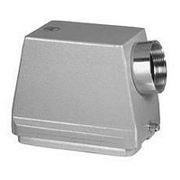
SIDE ENTRY HOOD, ALUMINUM ALLOY
Manufacturer
Amphenol-Tuchel Electronics
Datasheet
1.C146_10G024_506_8.pdf
(220 pages)
Specifications of C146-10G010-507-1
Cable Exit Angle
90°
Connector Body Material
Aluminum Alloy
Enclosure Material
Aluminum Alloy
Thread Size - Imperial
PG 21
Accessory Type
Side Entry Hood
For Use With
C146 Rectangular Connectors
Lead Free Status / RoHS Status
Lead free / RoHS Compliant


192
C 146
Technische Informationen
Technical information
Hinweise:
• Die Sicherheit von Steckverbindern/Steckverbinder mit Schaltleistung
• Verbindlich für den Einsatz von Steckverbindern sind die jeweiligen
• Alle Angaben der Bemessungsdaten der in diesem Katalog aufgeführten
• Alle technischen Angaben beziehen sich auf Steckverbinder, also
• Der Berührungsschutz der Kontakteinsätze im Anschlussbereich ist
• Beim Einbau der Steckverbinder in nicht leitende Gehäuse sind beide
• Ein ausführliches Kompendium von Steckverbinder-Begriffen befindet
• Nachstehend aufgeführte Auszüge aus Normen dienen der allgemeinen
• Prüfverfahren nach IEC 60512 entsprechen den Prüfverfahren nach
Anschlusstechniken
• Schraubverbindung
Tabelle 1
Die Ausziehkräfte (Streubereich) der Leiter aus einer Schraubverbindung
eines Kontaktelementes zeigt das untenstehende Diagramm 1 für eine
Klemmschraube M 3, angezogen mit einem Drehmoment von 50 Ncm.
Diagramm 1
Leiterquerschnitt (mm
Schraubengewinde
Prüfdrehmoment (Ncm) 40
Schraubklemmen werden nach EN 60999-1/VDE 0609 bemessen.
Die Gewindegröße in Abhängigkeit vom Leiterquerschnitt sowie das
dazugehörige Anzugs- und Prüfdrehmoment können untenstehender
Tabelle 1 entnommen werden.
(Steckvorrichtung) ist abhängig von der richtigen Auswahl der Produkte,
dem ordungsgemäßen Einbau und der sachgemäßen Montage.
Anforderungen der Gerätevorschriften. Dies gilt insbesondere für die
Festlegung der Bemessungsspannung und der damit zusammen-
hängenden Luft- und Kriechstrecken.
Steckverbindern sind auf die Überspannungskategorie III sowie den
Verschmutzungsgrad 3 (Anwendung im Maschinenbau) bezogen.
Betriebsmittel, die bei bestimmungsgemäßer Verwendung (unter
elektrischer Spannung) nicht gesteckt oder getrennt werden dürfen.
Soweit Steckverbinder im Sinne von Steckvorrichtungen (Steckverbinder
mit Schaltleistung) verwendet werden, ist dies in der Kurzinformation
der betreffenden Abschnitte aufgeführt.
durch den Einbau sicherzustellen.
Schutzleiter (Ausführung 2x PE) anzuschließen.
sich am Ende dieses Kapitels.
Information. Im konkreten Anwendungsfall sind die jeweils gültigen
Normen anzuwenden.
DIN EN 60512 oder DIN IEC 60512. Die DIN IEC 60664-1 entspricht
DIN VDE 0110-1
Allgemeine technische Informationen
Leiterquerschnitt
2
) 1
M 2,6 M 3
1,5
50
2,5
M 3
50
M 3,5 M 4
4
80
6
120
10
M 4
120
Remarks:
• The Safty of connectors/connectors with braking capacity (CBC)
• Decisions for the application of connectors are the requirements of the
• All rated data for the connectors listed in this catalogue is based on
• All technical data is specified for connectors, which are not under load
• Correct mounting will protect against electrical shock when mating the
• It connectors are mounted in non conductive housings both protective
• A detailed connector glossary can be found at the end of this catalogue.
• All mentioned excerpts of standards are for general information only.
• Test methods acc. IEC 60512 camply with test methods acc. DIN EN
Termination methods
• Screw connection
Chart 1
Diagram 1 below shows the range of tensile strength for a screw
connection with a clamp screw M3, fastened with a torque of 50 Ncm,
depending on the wire size.
Diagram 1
Wire size (mm
Screw size
Test torque (Ncm)
Screw clamps are designed acc. to EN 60999-1/VDE
0609. Chart 1 below shows the screw size depending
on wire size and the required clamping and testing
torque.
depends on the right selection of products, the correct installation and
a proper assembly.
equipment specifications. This is especially the case for the definition
of the rated voltage and the related clearances and creepage distances.
overvoltage category III and pollution degree 3 (machine tool
application).
when mated or disconnected. If in special cases connectors can be
used in the sense of plug and socket devices (connector with breaking
capacity), this is mentioned in the brief information of the particular
section.
connectors.
earthing terminals shall be mounted.
For specific cases the valid original standards have to be consulted.
60512 or DIN IEC 60512. IEC 60664-1 complies with DIN VDE 0110-1
General technical information
Wire gauge
2
)
1
M 2,6 M 3
40
1,5
50
2,5
M 3
50
4
M 3,5 M 4
80
6
120
Amphenol
10
M 4
120
Related parts for C146-10G010-507-1
Image
Part Number
Description
Manufacturer
Datasheet
Request
R

Part Number:
Description:
Heavy Duty Power Connectors PIN MODUL 10 WAY
Manufacturer:
Amphenol

Part Number:
Description:
Heavy Duty Power Connectors SOCKET MODULE 10 WAY
Manufacturer:
Amphenol

Part Number:
Description:
Heavy Duty Power Connectors PIN CONNECTOR 10 WAY
Manufacturer:
Amphenol

Part Number:
Description:
Heavy Duty Power Connectors FEMALE CONNECTOR 10 WAY
Manufacturer:
Amphenol

Part Number:
Description:
Male Receptacle 8+PE
Manufacturer:
Amphenol-Tuchel Electronics
Datasheet:

Part Number:
Description:
MEMORY CARD CONNECTOR, SMARTCARD
Manufacturer:
Amphenol-Tuchel Electronics
Datasheet:
Part Number:
Description:
Female Receptacle 8+PE
Manufacturer:
Amphenol-Tuchel Electronics
Part Number:
Description:
Male Cable Connector
Manufacturer:
Amphenol-Tuchel Electronics
Part Number:
Description:
Male Cable Connector
Manufacturer:
Amphenol-Tuchel Electronics
Part Number:
Description:
Specifications: Accessory Type: Cap (Cover) ; Color: Black ; Features: - ; For Use With/Related Products: Eco|mate
Manufacturer:
Amphenol-Tuchel Electronics