58448-3 Tyco Electronics, 58448-3 Datasheet - Page 2
58448-3
Manufacturer Part Number
58448-3
Description
Pro Crimper II SDE Die Set
Manufacturer
Tyco Electronics
Series
Pro-Crimper III, AMPLIMITE®r
Type
Pro Crimpersr
Specifications of 58448-3
Wire Size (awg)
28-20
Connector Type
Crimp Terminals
Crimp Handle
A9996-ND
Crimp Or Cable Size
20-28 AWG
Product
Crimping, Stripping & Cutting Tools & Drills
For Use With
Pro Crimper II Crimp Tool & D-Sub 20DF Pin & Socket Contacts AMPLIMITE
Lead Free Status / RoHS Status
na
Lead Free Status / RoHS Status
na, Not applicable / Not applicable
Other names
A9814


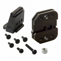
3. INSTALLATION AND REMOVAL OF DIE ASSEMBLY
2 of 5
Wire Crimper
AND LOCATOR ASSEMBLY
1. Open the tool handles, and remove the two die
retaining screws from the tool jaws.
2. Place the wire anvil and insulation anvil so that
the chamfered sides and marked surfaces face
outward, when mounted in the moving jaw of the
tool frame.
3. Insert the two short die retaining pins through
the tool frame and into the anvils.
4. Insert the short die retaining screw through the
jaw and through both anvil dies, and tighten the
screw just enough to hold the dies in place. Do not
tighten the screw completely at this time.
5. Place the wire crimper and insulation crimper so
that their chamfered sides and their marked
surfaces face outward, when mounted in the
stationary jaw of the tool frame.
6. Insert the two long die retaining pins (supplied
with the locator assembly) through the tool frame
and into the crimpers.
7. Insert the long die retaining screw through the
jaw and through both crimper dies, and tighten the
screw just enough to hold the dies in place. Do not
tighten the screw completely at this time.
8. Carefully close the tool handles, making sure
that the anvils and crimpers align properly.
Continue closing the tool handles until the ratchet
in the tool frame has engaged sufficiently to hold
Offset
Wire Anvil
Chamfered
Edge
Nut
Locator
Insulation
Anvil
(Figure 2)
Insulation
Crimper
Chamfered
Edge
Locator
Assembly
Figure 2
4. CRIMPING PROCEDURE
Refer to Figure 1, and select wire of the specified size
and insulation diameter. Strip the wire to the length
indicated, taking care not to nick or cut wire strands.
Select an applicable contact and identify the
appropriate crimping chamber according to the wire
size markings on the tool.
Refer to Figure 3, and proceed as follows:
NOTE
the anvils and crimpers in place, then tighten both
die retaining screws.
9. Remove the pin from the center hole in the
locator assembly. Place the locator assembly over
the end of the long die retaining screw and long die
retaining pins. Position the locator assembly
against the side of the tool jaw.
10. Place the nut onto the end of the long screw
and tighten the nut enough to hold the locator
assembly in place, while still allowing the locator to
slide up and down.
11. To disassemble, close the tool handles until the
ratchet releases, remove the nut, the locator
assembly, the two die retaining screws, and the
four die retaining pins, and slide the anvils and
crimpers out of the tool jaws.
i
Short Die Retaining
Screw
This tool is provided with a crimp adjustment
feature. Initially, the crimp height should be
verified as specified in Section 5, CRIMP
HEIGHT INSPECTION, and Section 6,
RATCHET (Crimp Height) ADJUSTMENT, before
using the tool to crimp desired contacts.
Tool Frame
Long Die Retaining Pins
(Supplied with Locator Assembly)
Short Die
Retaining Pins
Long Die Retaining
Screw
408- 9357
Rev E