MS3100F16S-4P ITT Cannon, MS3100F16S-4P Datasheet - Page 3
MS3100F16S-4P
Manufacturer Part Number
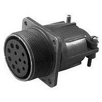
MS3100F16S-4P
Description
CIRCULAR CONN RCPT, SIZE 16S, 2POS, WALL
Manufacturer
ITT Cannon
Datasheet
1.MS3100E14S-6SF187.pdf
(15 pages)
Specifications of MS3100F16S-4P
Connector Body Material
Aluminum Alloy
Gender
Receptacle
Contact Gender
Pin
Connector Mounting
Wall
Connector Shell Size
16S
Insert Arrangement
16S-4
Connector Type
Circular Military
Lead Free Status / RoHS Status
Contains lead / RoHS non-compliant


MIL-C-5015 Connectors
* Not MSA/B insert arrangements and polarization.
MS Alternate Insert Positions
Shell
Size
10S
12
12S
14
14S
16
16S
18
20
8S
*
*
*
*
Arrange-
Contact
8S-1
10S-2
10SL-4
10SL-3
12-5
12S-4
12S-3
14-3
14S-1
14S-2
14S-5
14S-6
14S-7
14S-9
16-9
16-10
16-12
16-11
16-13
16S-1
16S-4
16S-5
16S-6
16S-8
18-1
18-3
18-4
18-5
18-7
18-8
18-9
18-10
18-11
18-12
18-13
18-15
18-19
18-22
20-2
20-3
20-4
20-7
20-8
20-14
20-15
20-16
20-17
20-18
20-19
ment
Wire
1 #16
1 #16
2 #16
3 #16
1 #12
1 #16
2 #16
1 #8
3 #16
4 #16
5 #16
6 #16
3 #16
2 #16
2 #16
2 #12
3 #12
1 #4
2 #12
2 #12
7 #16
2 #16
3 #16
3 #16
5 #16
10 #16
2 #12
4 #16
1 #16
2 #12
1 #8
7 #16
1 #12
5 #16
2 #12
4 #12
5 #12
6 #16
3 #12
1 #8
4 #12
10 #16
3 #16
1 #0
3 #12
4 #12
8 #16
4 #16
2 #8
3 #12
2 #8
7 #12
7 #16
2 #12
1 #16
5 #12
6 #16
3 #12
3 #8
Size
Inst.(all others)
Service Rating
D(A,B,G,H)
A(B,C,F,G)
A(C-F)
Inst.
Inst.
Inst.
Inst.
Inst.
A
A
A
A
D
D
A
A
A
A
A
A
A
A
A
A
A
D
A
A
A
D
D
D
B
A
A
A
A
A
A
A
D
D
D
D
A
A
A
A
A
A
Alternate Positions-Degrees
70
90
70
35
90
35
35
80
35
70
90
70
35
35
80
70
80
80
80
70
70
45
80
80
80
80
80
90
35
90
W
-
-
-
-
-
-
-
-
-
-
-
-
-
-
-
-
-
-
-
110
180
110
110
110
145
180
170
145
110
110
110
110
120
170
110
120
120
145
145
110
110
110
110
110
180
110
180
145
120
110
180
145
X
-
-
-
-
-
-
-
-
-
-
-
-
-
-
-
-
215
240
270
215
250
270
250
250
250
215
270
265
215
250
250
250
250
250
270
250
270
215
250
250
250
250
240
265
250
240
240
215
Y
-
-
-
-
-
-
-
-
-
-
-
-
-
-
-
-
-
290
280
325
290
290
325
325
280
290
280
280
280
290
290
280
280
280
280
280
325
290
325
325
325
Z
-
-
-
-
-
-
-
-
-
-
-
-
-
-
-
-
-
-
-
-
-
-
-
-
-
Shell
All views are looking into front of pin insert of rear of socket insert.
20
22
24
28
Size
*
*
*
*
*
*
*
*
*
Normal Position
Arrange-
Contact
20-22
20-23
20-24
20-27
20-29
20-33
22-2
22-4
22-5
22-6
22-7
22-9
22-10
22-11
22-12
22-13
22-14
22-15
22-17
22-18
22-19
22-20
22-22
22-23
22-27
22-28
24-2
24-5
24-6
24-7
24-9
24-10
24-11
24-12
24-20
24-22
24-27
24-28
28-1
28-2
28-7
28-9
ment
A
B
3 #16
3 #8
2 #8
2 #16
2 #8
14 #16
17 #16
11 #16
3 #8
2 #12
2 #8
4 #16
2 #12
1 #16
2 #8
1 #0
3 #12
4 #16
2 #16
3 #16
2 #8
1 #16
4 #12
19 #16
1 #16
5 #12
8 #16
1 #12
8 #16
14 #16
9 #16
4 #8
8 #12
8 #16
1 #8
7 #12
7 #12
16 #16
8 #12
14 #16
2 #12
2 #4
7 #8
6 #12
3 #8
3 #12
2 #4
9 #16
2 #12
4 #8
7 #16
24 #16
6 #12
3 #8
12 #16
2 #12
2 #4
6 #16
6 #12
Wire
Size
A(all others)
D(all others)
A(all others)
A(all others)
A(all others)
Service Rating
A(all others)
A(A-C,E,F)
D(A,G,H)
D)A,E,J)
A(A-D)
A(C-E)
D(H)
D(E)
E(D)
D(A)
D(J)
Inst.
D
D
D
A
A
A
A
A
A
D
A
D
D
E
E
E
B
D
A
A
A
A
A
A
A
A
A
A
A
E
D
D
D
Position W
Alternate Positions-Degrees
80
35
35
35
80
-
70
35
35
80
-
70
35
35
80
35
80
80
80
80
80
35
-
35
80
80
80
80
80
80
35
80
35
80
80
45
80
80
80
35
35
80
W
110
110
110
110
-
-
145
110
110
110
-
145
110
110
110
110
-
110
110
110
110
110
110
-
-
-
-
110
110
110
110
-
110
110
110
110
-
110
110
110
110
110
X
215
250
250
250
-
215
250
250
250
250
-
250
250
250
250
250
250
250
250
-
250
250
250
250
250
250
250
250
-
-
-
250
250
250
250
-
250
250
250
250
-
250
Y
280
325
325
325
280
-
290
325
325
280
-
290
325
325
280
325
280
280
280
280
280
325
-
-
280
280
280
325
325
280
280
280
280
280
325
280
325
280
280
-
280
280
Position X
Z
Shell
28
32
36
40
44
48
Size
*
*
*
*
*
*
*
*
*
Arrange-
28-10
28-11
28-12
28-15
28-16
28-17
28-19
28-20
28-21
28-22
32-1
32-6
32-7
32-8
32-9
32-15
32-17
36-4
36-5
36-6
36-7
36-8
36-9
36-10
36-14
36-15
40-10
40-56
44-1
48-5
Contact
ment
3 #12
2 #8
2 #4
18 #16
4 #12
26 #16
35 #16
20 #16
15 #16
6 #16
4 #12
4 #16
10 #16
37 #16
3 #16
3 #4
3 #12
2 #0
16 #16
2 #12
3 #8
2 #4
28 #16
7 #12
24 #16
6 #12
12 #16
2 #4
2 #0
6 #12
4 #4
3 #0
4 #0
4 #4
2 #0
40 #16
7 #12
46 #16
1 #12
14 #16
14 #12
2 #8
1 #4
48 #16
6 #16
5 #12
5 #8
35 #16
16 #16
9 #8
4 #4
85 #16
36 #16
6 #12
90 #16
1 #8
9 #12
Wire
Size
Dimensions are shown in inches (millimeters).
Position Y
B(H,M), D(A,B)
A(C,E,G,J,K,L)
Inst. (A,B,h,j)
Service Rating
D(all others)
A(all others)
A(A-L),B(R)
A(all others)
A(all others)
MS-E/F/R/ER
D(M-P)
A(B,C)
D (m)
D(G)
E(A)
D(A)
D
D
D
D
D
D
A
A
A
A
A
A
A
A
A
A
A
A
A
A
A
A
A
Dimensions subject to change.
www.ittcannon.com
Alternate Positions-Degrees
80
80
90
80
80
80
80
80
80
70
80
80
80
80
80
35
45
70
-
35
80
80
80
80
90
60
65
72
65
65
W
Position Z
110
110
180
110
110
110
110
110
110
145
110
110
125
125
110
110
110
145
120
110
110
110
125
125
180
125
125
144
125
125
X
250
250
270
250
250
250
250
250
250
215
250
250
235
235
250
250
250
215
240
250
250
250
235
235
270
245
225
216
225
225
Y
280
280
-
280
280
280
280
280
280
290
280
280
280
280
280
280
-
290
-
325
280
280
280
280
-
305
310
288
310
310
Z
169
Related parts for MS3100F16S-4P
Image
Part Number
Description
Manufacturer
Datasheet
Request
R

Part Number:
Description:
CIRCULAR CONN, RCPT, SIZE 32, 4POS, WALL
Manufacturer:
ITT Cannon
Datasheet:

Part Number:
Description:
3 Amp Schottky Rectifier
Manufacturer:
MICROSEMI [Microsemi Corporation]
Datasheet:

Part Number:
Description:
EMI SHIELDED ENDBELL WITH 4-40 EXTENDED JACKSCREW
Manufacturer:
ITT Cannon
Datasheet:
Part Number:
Description:
UNIVERSAL CONTACT 1.8MM SMD
Manufacturer:
ITT Cannon
Datasheet:
Part Number:
Description:
UNIVERSAL CONTACT 2.5MM SMD
Manufacturer:
ITT Cannon
Datasheet:
Part Number:
Description:
UNIVERSAL CONTACT 3.5MM SMD
Manufacturer:
ITT Cannon
Datasheet:
Part Number:
Description:
PLUG STR CRIMP SMB RG174/U 316/U
Manufacturer:
ITT Cannon
Datasheet:
Part Number:
Description:
TRI TNM RECP M FLG SEAL 0-12
Manufacturer:
ITT Cannon
Datasheet:
Part Number:
Description:
CONN RCPT 6POS JAM NUT W/SCKT
Manufacturer:
ITT Cannon
Datasheet:

Part Number:
Description:
TRI R E/B STR C/C SEAL SZ 18
Manufacturer:
ITT Cannon
Datasheet:
Part Number:
Description:
CAB CON 16S PIN 18/16 F80 SILVER
Manufacturer:
ITT Cannon
Datasheet:

Part Number:
Description:
TRI CON SKT 16-18 TIN ST/LO
Manufacturer:
ITT Cannon
Datasheet:

Part Number:
Description:
TRI CON PIN 20-22 TIN ST/LO
Manufacturer:
ITT Cannon
Datasheet:
Part Number:
Description:
TRI CON SKT 16 GLD MACH NOINS
Manufacturer:
ITT Cannon
Datasheet: