166500-2 Tyco Electronics, 166500-2 Datasheet - Page 5
166500-2
Manufacturer Part Number
166500-2
Description
CONTACT, SOCKET, 24-20AWG, CRIMP
Manufacturer
Tyco Electronics
Series
AMPMODUr
Type
Signalr
Specifications of 166500-2
Connector Type
Wire To Board Contact
Contact Plating
Gold
Contact Material
Phosphor Bronze
Wire Size (awg)
24-20
Contact Termination
Crimp
Pin Or Socket
Socket
Wire Gauge
20-24 AWG
Contact Finish
Gold
Contact Finish Thickness
30µin (0.76µm)
Product Type
Contacts
Contact Gender
Socket (Female)
Mounting Style
Wire
Termination Style
Crimp
Wire Gauge Range
24-20
Current Rating
3 A
For Use With
AMPMODU Connectors
Lead Free Status / RoHS Status
Lead free / RoHS Compliant
Lead Free Status / RoHS Status
Lead free / RoHS Compliant, Lead free / RoHS Compliant
Available stocks
Company
Part Number
Manufacturer
Quantity
Price
Company:

Part Number:
166500-2
Manufacturer:
TE
Quantity:
20 000


Rev D
B. Effective Crimp Length
For optimum crimp effectiveness, the crimp must be within the area shown and must meet the crimp
dimensions provided in Figure 3. Effective crimp length shall be defined as that portion of the wire barrel,
excluding bellmouth(s), fully formed by the crimping tool. Instructions for adjusting, repairing, and
inspecting tools are packaged with the tools. See Section 5, TOOLING.
C. Bellmouths
Front and rear bellmouths shall be evident and conform to the dimensions given in Figure 3.
D. Cutoff Tabs
The cutoff tab shall be cut to the dimensions shown in Figure 3.
E. Burrs
The cutoff burr shall not exceed the dimensions shown in Figure 3.
F. Wire Barrel Flash
The wire barrel flash shall not exceed the dimensions shown in Figure 3, Section X--X.
G. Insulation Barrel Crimp
The insulation barrel shall grip the insulation firmly without cutting into it. Care must be taken to prevent
cutting, nicking, or scraping of the insulation. Insulation crimp shall comply to width and height provided in
Figure 3.
H. Wire Location
The wire conductor and insulation must be visible in the transition area between the wire and insulation
barrels.
I. Conductor Extension
The conductor may extend beyond the wire barrel to the maximum shown.
J. Wire Barrel Seam
The wire barrel seam must be closed with no evidence of loose wire strands visible in the seam.
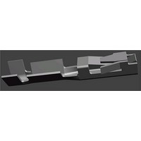
K. Twist and Roll
There shall be no twist, roll, deformation or other damage to the mating portion of the crimped contact that
will impair usage of the contact. See Figure 4.
L. Straightness
The force applied during crimping may cause some bending between the crimped wire barrel and the
mating portion of the contact. Such deformation is acceptable within the limits provided in Figure 5.
1. The up and down bend of the crimped contact, including cutoff tab and burr, shall not be bent above
or below the datum line more than the amount shown.
Figure 4
No Twist Permitted
Wire Barrel
114- 25021
5 of 18
Related parts for 166500-2
Image
Part Number
Description
Manufacturer
Datasheet
Request
R

Part Number:
Description:
Battery Interconnection System for Portable Electronics; BU CONN FS6 8POS DIP TYPE ASSY ( AMP )
Manufacturer:
Tyco Electronics
Part Number:
Description:
Manufacturer:
Tyco Electronics
Datasheet:
Part Number:
Description:
Manufacturer:
Tyco Electronics
Datasheet:
