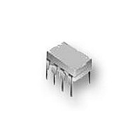
IL710T-2E NVE, IL710T-2E Datasheet

IL710T-2E
Specifications of IL710T-2E
Related parts for IL710T-2E
IL710T-2E Summary of contents
Page 1
... Valley View Road, Eden Prairie, MN 55344-3617 Features • +5 V/+3.3 V CMOS / TTL Compatible • High Speed: 150 Mbps Typical (IL710S) • High Temperature: −40°C to +125°C (IL710T) • 2500 V Isolation (1 min.) RMS • 300 ps Typical Pulse Width Distortion (IL710S) • ...
Page 2
... Output Voltage Output Current Drive Lead Solder Temperature ESD Recommended Operating Conditions Parameters Ambient Operating Temperature IL710 and IL710S IL710T Supply Voltage Logic High Input Voltage Logic Low Input Voltage Input Signal Rise and Fall Times Insulation Specifications Parameters Creepage Distance ...
Page 3
IL710 Pin Connections 1 V Supply voltage DD1 2 IN Data internal connection 4 GND Ground return for V 1 DD1 5 GND Ground return for V 2 DD2 6 OUT Data Out Output enable. 7 ...
Page 4
... Propagation Delay Enable to Output (Low to High Impedance) Propagation Delay Enable to Output (High Impedance to High) Propagation Delay Enable to Output (High Impedance to Low) (2) Pulse Width Distortion IL710 and IL710T IL710S (8) Pulse Jitter (3) Propagation Delay Skew Output Rise Time (10%–90%) Output Fall Time (10%–90%) ...
Page 5
... Propagation Delay Enable to Output (Low to High Impedance) Propagation Delay Enable to Output (High Impedance to High) Propagation Delay Enable to Output (High Impedance to Low) (2) Pulse Width Distortion IL710 and IL710T IL710S (3) Propagation Delay Skew Output Rise Time (10%–90%) Output Fall Time (10%–90%) Common Mode Transient Immunity (4) ...
Page 6
... IsoLoop Isolators achieve their low power consumption from the way they transmit data across the isolation barrier. By detecting the edge transitions of the input logic signal and converting these to narrow current pulses, a magnetic field is created around the GMR Wheatstone bridge. Depending on the direction of the magnetic field, the bridge causes the output comparator to switch following the input logic signal ...
Page 7
... Application Diagrams Isolated PROFIBUS / RS-485 Isolation Boundary IL710 IL710 IL710 NVE offers a unique line of PROFIBUS/RS-485 transceivers, but IL710 isolators can also be used as part of multi-chip designs using non- isolated PROFIBUS transceivers. RS-485 Truth Table TXD RTS Note: ISL8485 V and V should be decoupled with ...
Page 8
... USBOE In this circuit, power is supplied by USB bus power on one side of the isolation barrier, and the USB node’s external supply on the other side of the barrier. IL700 Isolators are specified with just 3 ns worst-case pulse width distortion. Isolation Boundary 5 x IL710 ...
Page 9
Package Drawings, Dimensions and Specifications 8-pin MSOP 0.114 (2.90) 0.122 (3.10) 0.114 (2.90) 0.189 (4.80) 0.197 (5.00) 0.122 (3.10) 0.010 (0.25) 0.016 (0.40) 8-pin SOIC Package 0.189 (4.8) 0.197 (5.0) 0.228 (5.8) 0.150 (3.8) 0.244 (6.2) 0.157 (4. ...
Page 10
... Valid Part Numbers IL710-1E IL710S-1E Bulk Packaging IL710T-1E Blank = Tube TR7 = 7" Tape and Reel IL710-2 TR13 = 13" Tape and Reel IL710T-2 IL710-2E Package IL710T-2E Blank = 80/20 Tin/Lead Plating E = RoHS Compliant IL710-3 IL710S-3 Package Type IL710T MSOP IL710- PDIP IL710S- 0.15" 8-pin SOIC ...
Page 11
... Corrected PWD spec. on Isolated USB application diagram (p. 8). • Changed lower limit of length on PDIP package drawing and ISB-DS-001-IL710-N Changes • Changed IL710T output quiescent supply current specifications. ISB-DS-001-IL710-M Changes • Changed ordering information to reflect that devices are now fully RoHS compliant with ...
Page 12
... Corporation for its use, nor for any infringement of patents, nor rights or licenses granted to third parties, which may result from its use. No license is granted by implication, or otherwise, under any patent or patent rights of NVE Corporation. NVE Corporation does not authorize, nor warrant, any NVE Corporation product for use in life support devices or systems or other critical applications, without the express written approval of the President of NVE Corporation ...


