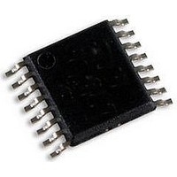
THAT1606Q16-U THAT Corporation, THAT1606Q16-U Datasheet - Page 7

THAT1606Q16-U
Manufacturer Part Number
THAT1606Q16-U
Description
LINE DRIVER, BALANCED, SMD, 1606
Manufacturer
THAT Corporation
Datasheet
1.1606Q16-U.pdf
(12 pages)
Specifications of THAT1606Q16-U
Device Type
Differential
Supply Voltage Range
± 4V To ± 18V
Driver Case Style
QSOP
No. Of Pins
16
Operating Temperature Range
-40°C To +85°C
Operating Temperature Max
85°C
Operating Temperature
RoHS Compliant
Base Number
1606
Gain Over Bandwidth
6dB
Rohs Compliant
Yes
Available stocks
Company
Part Number
Manufacturer
Quantity
Price
Part Number:
THAT1606Q16-U
Manufacturer:
THATCORP
Quantity:
20 000
i
THAT1606/1646 Balanced Line Driver ICs
for various types of music and speech will be flat out
to 5kHz, and roll off at 6dB/octave above this fre-
quency. Thus the peak levels at 20kHz will be 12dB
below those at 5kHz.
rate and current drive. For the +26 dBu output lev-
els that the 1646 is capable of, VPeak is 22V (below
5kHz), and at 20kHz, VPeak is 5.5V. Therefore,
As a consequence,
mA
1606 and 1646.
Gain structure
tor of 2) between their inputs and differential out-
puts.
output, twice the voltage between the power supply
rails is available at the output of the stage. The sin-
gle-ended input of the 1646 can accept signals that
swing to nearly the power supply rails without distor-
tion, when driving into a differential (floating) load.
The balanced input of the 1606 can accept signals at
each input that swing to nearly one-half the power
supply rails without distortion, when driving into dif-
ferential loads.
=
500
Peak
Using these, we can calculate the required slew
Thus, driving this 25.25 nF cable requires 17.5
The 1606 and 1646 both provide +6 dB gain (fac-
dV
dt
=
, which is well within the capability of the
ft
This is appropriate, since with a balanced
2
×
p
(
×
34
5 5
.
pF
ft
V
×
+
16 5
THAT Corporation; 45 Sumner Street; Milford, Massachusetts 01757-1656; USA
20
.
Tel: +1 (508) 478-9200; Fax: +1 (508) 478-0990; Web: www.thatcorp.com
kHz
pF
Figure 5. THAT 1646 application circuit with common-mode offset reduction
ft
In
)
=
×
100n
0 69
0 69
100n
.
Copyright © 2007, THAT Corporation; All rights reserved.
.
C4
C5
m
V
m
s
V
s
=
17 5
4
3
.
In
Gnd
mA
Vcc
Vee
Vee
Vcc
.
Sns+
Sns-
Page 7 of 12
Out+
Out-
U1
THAT1646
10u
NP
C1
8
1
10u
C2
NP
will clip at about half the output voltage as compared
to a differential load. This is because only one of the
two output signals will be available. Despite the out-
put clipping, the input to the devices does not need to
be constrained - they will work without undue prob-
lems being overdriven at their inputs when the out-
puts are clipping into single-ended loads.
1646 circuits
1646. The only external components needed are the
local 100nF bypass capacitors.
within 1 inch of the 1646 pins.
Output DC offset
to their respective sense inputs, this circuit may pro-
duce up to 250mV of common-mode dc offset at its
outputs. As shown, the outputs are DC coupled to
the output connector, so this dc will appear directly
at the output of the system.
be reduced by adding capacitors in the feedback
loop, as shown in Figure 5. Capacitors C1 and C2
ac-couple the common-mode feedback loop.
changes the loop operation from servoing the com-
mon-mode output current at audio frequencies to
servoing the common-mode output voltage to 0 at
DC. This results in much lower common-mode out-
put offset voltage, as indicated in the specifications
section. C1 and C2 are typically high quality
non-polarized electrolytic capacitors.
Both devices, when driving single-ended loads,
Figure 4 shows the most basic connection for a
Because the 1646's outputs are connected directly
The output common-mode offset of a 1646 may
XLR (M)
1
3
2
Document 600078 Rev 04
These should be
This


