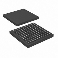
PIC32MX440F128L-80I/BG Microchip Technology, PIC32MX440F128L-80I/BG Datasheet - Page 4

PIC32MX440F128L-80I/BG
Manufacturer Part Number
PIC32MX440F128L-80I/BG
Description
IC, 32BIT MCU, PIC32, 80MHZ, BGA-100
Manufacturer
Microchip Technology
Series
PIC® 32MXr
Datasheets
1.MA320002.pdf
(208 pages)
2.DM320001.pdf
(44 pages)
3.PIC32MX320F032H-40IPT.pdf
(48 pages)
4.PIC32MX320F032H-40IPT.pdf
(66 pages)
5.PIC32MX320F032H-40IPT.pdf
(22 pages)
6.PIC32MX320F064H-40IMR.pdf
(172 pages)
Specifications of PIC32MX440F128L-80I/BG
Controller Family/series
PIC32
Ram Memory Size
32KB
Cpu Speed
80MHz
No. Of Timers
5
Interface
EUSART, I2C, SPI, USB
No. Of Pwm Channels
5
Core Size
32 Bit
Program Memory Size
128 KB
Core Processor
MIPS32® M4K™
Speed
80MHz
Connectivity
I²C, IrDA, LIN, PMP, SPI, UART/USART, USB OTG
Peripherals
Brown-out Detect/Reset, DMA, POR, PWM, WDT
Program Memory Type
FLASH
Ram Size
32K x 8
Voltage - Supply (vcc/vdd)
2.3 V ~ 3.6 V
Data Converters
A/D 16x10b
Oscillator Type
Internal
Operating Temperature
-40°C ~ 85°C
Package / Case
121-TFBGA
Embedded Interface Type
EUSART, I2C, SPI, USB
Rohs Compliant
Yes
Processor Series
PIC32MX4xx
Core
MIPS
Data Bus Width
32 bit
Data Ram Size
32 KB
Interface Type
EUART, I2C, SPI
Maximum Clock Frequency
80 MHz
Number Of Programmable I/os
85
Number Of Timers
5
Maximum Operating Temperature
+ 85 C
Mounting Style
SMD/SMT
3rd Party Development Tools
52713-733, 52714-737
Development Tools By Supplier
PG164130, DV164035, DV244005, DV164005, DM320003, DM320002, MA320002
Minimum Operating Temperature
- 40 C
On-chip Adc
10 bit, 16 Channel
Lead Free Status / RoHS Status
Lead free / RoHS Compliant
For Use With
876-1000 - PIC32 BREAKOUT BOARD
Number Of I /o
-
Eeprom Size
-
Lead Free Status / Rohs Status
Details
Available stocks
Company
Part Number
Manufacturer
Quantity
Price
Company:
Part Number:
PIC32MX440F128L-80I/BG
Manufacturer:
Microchip Technology
Quantity:
10 000
PIC32MX3XX/4XX
TABLE 2:
DS80440D-page 4
Note 1:
Oscillator
Oscillator
Compare
Compare
Compare
Prefetch
Program
Memory
Module
Timers
Output
Output
Output
Cache
UART
UART
Flash
ADC
ADC
DMA
USB
USB
USB
USB
USB
SPI
Only those issues indicated in the last column apply to the current silicon revision.
Signal Source
Programming
5V Tolerance
CRC Append
Clock Switch
Clock Switch
Fault Mode
SILICON ISSUE SUMMARY (CONTINUED)
Transition
Operation
Detection
Feature
Clock
Mode
SE0
—
—
—
—
—
—
—
—
—
—
Number
Item
29.
30.
31.
32.
33.
34.
35.
36.
37.
38.
39.
40.
41.
42.
43.
44.
45.
46.
47.
Enabling the primary programming/debug port (PGC1/
PGD1) on 64 lead variants disables the external and
internal references for the ADC, making the ADC
unusable.
Firmware clock switch requests to switch from FRC mode,
after a FSCM event, may fail.
The D+ and D– pins are not 5V tolerant.
The single-ended comparator detects SE0 transitions at a
voltage higher than the USB specification.
If the Predictive Prefetch Cache Enable bits
(PREFEN<1:0>) in the CHECON register are non-zero,
improper processor behavior may occur during a rare
boundary condition.
NVM registers must not be written immediately after a
programming operation is complete.
When the ADC is in operation, the current channel is
shorted to V
after sampling.
Writes to the timer registers PRx and TIMERx through the
Set/Clear/Invert registers corrupts the data written.
The USB clock does not automatically suspend when
entering Sleep mode.
The TRMT bit is asserted before the transmission is
complete.
PWM fault override is not asynchronous.
The SPIBUSY and SRMT bits assert 1 bit time before the
end of the transaction.
Faults may be cleared erroneously due to an aborted
read.
The TOKBUSY bit does not correctly indicate status when
a transfer completes within the Start of Frame (SOF)
threshold.
The interval between the first two SOF packets generated
does not meet USB specification.
If firmware clears a PWM Fault while a Fault condition is
asserted, an interrupt will not be generated for the current
Fault.
Clock switching and Two-Speed Start-up may cause a
general exception when the reserved bit 8 of the DDPCON
register is ‘0’.
The RXDA bit does not correctly reflect the RX FIFO
status after an overrun event.
In Pattern Match mode, the DMA module may not append
all of the CRC results to the result buffer.
REF
during the conversion period (12 T
Issue Summary
© 2010 Microchip Technology Inc.
AD
)
B2 B3 B4 B6
X
X
X
X
X
X
X
X
X
X
X
X
X
X
X
X
X
X
X
Revisions
Affected
X
X
X
X
X
X
X
X
X
X
X
X
X
X
X
X
X
X
X
X
X
X
X
X
X
X
X
X
X
X
(1)
X
X
X
X
X
X
X
X
X
X
X
X
X
X


