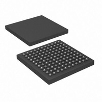
PIC32MX675F256L-80I/BG Microchip Technology, PIC32MX675F256L-80I/BG Datasheet - Page 17

PIC32MX675F256L-80I/BG
Manufacturer Part Number
PIC32MX675F256L-80I/BG
Description
IC, 32BIT MCU, PIC32, 80MHZ, BGA-100
Manufacturer
Microchip Technology
Series
PIC® 32MXr
Datasheets
1.PIC32MX320F032H-40IPT.pdf
(66 pages)
2.PIC32MX575F256H-80IMR.pdf
(2 pages)
3.PIC32MX575F256H-80IMR.pdf
(254 pages)
4.PIC32MX575F256H-80IMR.pdf
(14 pages)
5.PIC32MX575F256H-80IPT.pdf
(240 pages)
Specifications of PIC32MX675F256L-80I/BG
Controller Family/series
PIC32
Ram Memory Size
64KB
Cpu Speed
80MHz
No. Of Timers
5
Interface
I2C, SPI, UART, USB
No. Of Pwm Channels
5
Core Size
32 Bit
Program Memory Size
256 KB
Core Processor
MIPS32® M4K™
Speed
80MHz
Connectivity
Ethernet, I²C, SPI, UART/USART, USB OTG
Peripherals
Brown-out Detect/Reset, DMA, POR, PWM, WDT
Program Memory Type
FLASH
Ram Size
64K x 8
Voltage - Supply (vcc/vdd)
2.3 V ~ 3.6 V
Data Converters
A/D 16x10b
Oscillator Type
Internal
Operating Temperature
-40°C ~ 85°C
Package / Case
121-TFBGA
Embedded Interface Type
I2C, SPI, UART, USB
Rohs Compliant
Yes
Lead Free Status / RoHS Status
Lead free / RoHS Compliant
Number Of I /o
-
Eeprom Size
-
Lead Free Status / RoHS Status
Lead free / RoHS Compliant, Lead free / RoHS Compliant
Available stocks
Company
Part Number
Manufacturer
Quantity
Price
Company:
Part Number:
PIC32MX675F256L-80I/BG
Manufacturer:
Microchip Technology
Quantity:
10 000
8.0
Before a device can be programmed, the programmer
must check the status of the device to ensure that it is
ready to receive information.
FIGURE 8-1:
© 2010 Microchip Technology Inc.
CHECK DEVICE STATUS
statusVal = XferData (MCHP_STATUS)
No
SendCommand (MTAP_COMMAND)
SendCommand (MTAP_SW_MTAP)
SetMode (6’b011111)
Set MCLR low
CFGRDY = 1
CHECK DEVICE STATUS
FCBUSY = 0
Done
Yes
4-Wire
8.1
Four-wire JTAG programming is a Mission mode
operation and therefore the setup sequence to begin
programing should be done while asserting MCLR.
Holding the device in Reset prevents the processor
from executing instructions or driving ports.
The following steps are required to check the device
status using the 4-wire interface:
1.
2.
3.
4.
5.
6.
8.2
The following steps are required to check the device
status using the 2-wire interface:
1.
2.
3.
4.
5.
Note:
Set MCLR pin low.
SetMode (6’b011111) to force the Chip TAP
controller into Run Test/Idle state.
SendCommand (MTAP_SW_MTAP).
SendCommand (MTAP_COMMAND).
statusVal = XferData (MCHP_STATUS).
If CFGRDY (statusVal<3>) is not ‘1’ and
FCBUSY (statusVal<2>) is not ‘0’ GOTO step 5.
SetMode (6’b011111) to force the Chip TAP
controller into Run Test/Idle state.
SendCommand (MTAP_SW_MTAP).
SendCommand (MTAP_COMMAND).
statusVal = XferData (MCHP_STATUS).
If CFGRDY (statusVal<3>) is not ‘1’ and
FCBUSY (statusVal<2>) is not ‘0’, GOTO
step 4.
4-Wire Interface
2-Wire Interface
If CFGRDY and FCBUSY do not come to
the proper state within 10 ms, the
sequence may have been executed wrong
or the device is damaged.
PIC32MX
DS61145G-page 17


