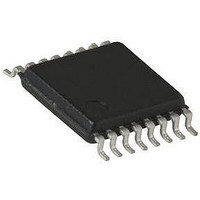
SI9731DQ-T1 Vishay, SI9731DQ-T1 Datasheet - Page 8

SI9731DQ-T1
Manufacturer Part Number
SI9731DQ-T1
Description
IC, BATTERY CHARGER, TSSOP-16
Manufacturer
Vishay
Type
Charge Controllerr
Datasheet
1.SI9731DQ-T1.pdf
(10 pages)
Specifications of SI9731DQ-T1
Output Voltage
4.1V
No. Of Pins
16
Operating Temperature Range
-40°C To +85°C
Peak Reflow Compatible (260 C)
No
Leaded Process Compatible
No
Battery Type
Li-Ion/NiCD/NiMH
Output Current
1.2A
Operating Temp Range
-40C to 85C
Package Type
TSSOP
Mounting
Surface Mount
Pin Count
16
Operating Temperature Classification
Industrial
Maximum Operating Temperature
+ 85 C
Minimum Operating Temperature
- 40 C
Package / Case
TSSOP-16
Mounting Style
SMD/SMT
Lead Free Status / RoHS Status
Contains lead / RoHS non-compliant
Available stocks
Company
Part Number
Manufacturer
Quantity
Price
Company:
Part Number:
SI9731DQ-T1
Manufacturer:
Infineon
Quantity:
12 000
Company:
Part Number:
SI9731DQ-T1-E3
Manufacturer:
FUJI
Quantity:
3 000
Part Number:
SI9731DQ-T1-E3
Manufacturer:
VISHAY/威世
Quantity:
20 000
Si9731
Vishay Siliconix
DETAIL OPERATIONAL DESCRIPTION
Si9731 is a chemistry independent battery charger designed
for use with a system processor. For example, Si9731 can be
integrated within a cellular phone whereby the fast charge
and trickle (slow) charge modes can be software controlled
by the DSP. The device is designed to charge 1-cell Li-ion or
1-cell to 3-cell NiCd/NiMH batteries. A regulated or
unregulated external dc power source such as a wall adapter
rated at typically 4.5 V to 12 V is connected to Si9731’s
V
is comprised of a transformer, bridge rectifier and a reservoir
capacitor. The wall adaptor’s output voltage decreases
linearly with increase in output current. When Si9731 is fast
charging the battery, the wall adaptor’s output voltage tracks
the battery voltage plus the voltage drop across Q1 (charging
current times MOSFET Q1’s R
features of Si9731 are described below.
Since the under voltage lock out (UVLO) point of Si9731 is
2.6 V (typical), it is essential to keep the charger voltage
above this level under all conditions, especially for fast
charging of single cell NiCd/NiMH. One simple solution is
adding a external resistor between V
which creates extra voltage drop to elevate the charger
voltage. The value of the resistor is affected by the output
V-I characteristic of the ac charger.
Trickle Charge
The charge path is via N-Channel MOSFETs Q1 or Q2 (see
applications circuit of Figure 1). Si9731 defaults to trickle
(slow) charge mode if the battery voltage is too low to power
the main processor. With the main processor unable to drive
the
TRICKLECHARGEEN pins, Q1 is turned "OFF" preventing
fast charging. Meanwhile N-Channel MOSFET Q2 turns
"ON" and establishes a trickle charge path from the external
power source V
current is set by an external current limiting resistor, R
is approximately I
the battery voltage charges up to minimum battery operating
voltage 3.24 V, the internal latch is triggered and the
CHARGERPOWER_ON output changes state to wake up
the processor. The processor is now able to disable trickle
charge mode by taking the TRICKLECHARGEEN pin high
while
MAINCHARGEEN pin.
www.vishay.com
8
CHARGER
MAINCHARGEEN
taking
input pin. Note that a typical low cost wall adaptor
CHARGER
control
TRICKLE
to the battery. The trickle charge
= (V
of
pin
CHARGER
DS(on)
fast
BAT+
, see Figure 1). The key
as
charging
- V
pin and the battery,
well
BAT+
)/R
as
ext
via
ext
. Once
, and
the
the
Fast Charge
Fast charging is accomplished by the low "ON" resistance
MOSFET, Q1. The application microprocessor is able to
"Pulse Charge" the battery via the MAINCHARGEREN
control input of Si9731. The processor monitors the battery
voltage via the system A/D converter and varies the pulse
charging duty cycle accordingly to maintain fast charging.
Note that even though charging current may be sufficiently
high, pulse charging with short "ON" time and long "OFF"
time ensures that heat generation due to thermal heating is
reduced.
In the case of NiCd or NiMH batteries, one of several charge
termination schemes may be used to terminate charge. For
example, the processor may disable fast charging by
sensing ΔV or dV/dt at the V
temperature differential ΔT of the battery. Following fast
charge, trickle charge may be enabled to "top off" the battery.
When charging a 1-cell Li-ion battery, fast charging will
operate in two modes, constant current mode followed by
constant voltage mode. In the constant current mode, a
discharged Li-ion battery is charged with constant current
available from the external dc source. The MOSFET pass
transistor (Q1) may be pulsed "ON" and "OFF" at varying
duty
MAINCHARGEEN input pin. Once the battery voltage
reaches it’s termination voltage of 4.1 V or 4.2 V (depending
on the connection of the 4.1 V
the "Constant Voltage" charging mode by taking the
CVMODE pin high. Taking CVMODE pin high disables trickle
charging and enables the internal battery voltage divider by
turning ON Q5. Then the error amplifier will compare divided
V
reference voltage (see Figure 1). The output of the error
amplifier drives the pass transistor Q1 to maintain V
the regulated termination voltage. This operation is same as
a linear regulator.
True Load Disconnect
Both the fast charge FET (Q1 in Figure 1) and trickle charge
FET (Q2 in Figure 1) incorporate a floating body diode. In
their "OFF" state both FETs block current bidirectionally.
Note that because of the reverse blocking switches, a
Schottky diode in series with the external V
supply is not required.
BAT+
cycle
voltage against an internal precision 1.3 V bandgap
by
the
control
BAT+
TAP
output or by monitoring the
), Si9731 may be placed in
signal
S09-2249-Rev. C, 26-Oct-09
Document Number: 71321
present
CHARGER
at
BAT+
power
the
at


