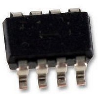
LT3470ITS8#PBF Linear Technology, LT3470ITS8#PBF Datasheet - Page 10

LT3470ITS8#PBF
Manufacturer Part Number
LT3470ITS8#PBF
Description
IC, BUCK REGULATOR, 8-TSOT-23
Manufacturer
Linear Technology
Datasheet
1.LT3470ITS8PBF.pdf
(20 pages)
Specifications of LT3470ITS8#PBF
Primary Input Voltage
40V
No. Of Outputs
1
Output Voltage
16V
Output Current
200mA
No. Of Pins
8
Operating Temperature Range
-40°C To +125°C
Termination Type
SMD
Dc To Dc Converter Type
Step Down
Number Of Outputs
1
Pin Count
8
Input Voltage
40V
Package Type
TSOT-23
Output Type
Adjustable
Switching Regulator
Yes
Line Regulation
0.01%/V
Mounting
Surface Mount
Input Voltage (min)
4V
Operating Temperature Classification
Automotive
Msl
MSL 1 - Unlimited
Rohs Compliant
Yes
Lead Free Status / RoHS Status
Lead free / RoHS Compliant
Lead Free Status / RoHS Status
Lead free / RoHS Compliant
Available stocks
Company
Part Number
Manufacturer
Quantity
Price
APPLICATIO S I FOR ATIO
LT3470
be used. It is important to note that inductor saturation
current is reduced at high temperatures—see inductor
vendors for more information.
Input Capacitor
Step-down regulators draw current from the input supply
in pulses with very fast rise and fall times. The input
capacitor is required to reduce the resulting voltage ripple
at the V
current into a tight local loop, minimizing EMI. The input
capacitor must have low impedance at the switching
frequency to do this effectively. A 1µF to 2.2µF ceramic
capacitor satisfies these requirements.
If the input source impedance is high, a larger value
capacitor may be required to keep input ripple low. In this
case, an electrolytic of 10µF or more in parallel with a 1µF
ceramic is a good combination. Be aware that the input
capacitor is subject to large surge currents if the LT3470
circuit is connected to a low impedance supply, and that
some electrolytic capacitors (in particular tantalum) must
be specified for such use.
Output Capacitor and Output Ripple
The output capacitor filters the inductor’s ripple current
and stores energy to satisfy the load current when the
LT3470 is quiescent. In order to keep output voltage ripple
low, the impedance of the capacitor must be low at the
10
IN
pin of the LT3470 and to force this switching
Table 2. Inductor Vendors
VENDOR
Coilcraft
Sumida
Toko
Würth Elektronik
Coiltronics
Murata
U
U
URL
www.coilcraft.com
www.sumida.com
www.tokoam.com
www.we-online.com
www.cooperet.com
www.murata.com
W
U
PART SERIES
DO1605
ME3220
DO3314
CR32
CDRH3D16/HP
CDRH3D28
CDRH2D18/HP
DB320C
D52LC
WE-PD2 Typ S
WE-TPC Typ S
SD10
LQH43C
LQH32C
LT3470’s switching frequency. The capacitor’s equivalent
series resistance (ESR) determines this impedance. Choose
one with low ESR intended for use in switching regulators.
The contribution to ripple voltage due to the ESR is
approximately I
The value of the output capacitor must be large enough to
accept the energy stored in the inductor without a large
change in output voltage. Setting this voltage step equal to
1% of the output voltage, the output capacitor must be:
Where I
Electrical Characteristics). For example, an LT3470 pro-
ducing 3.3V with L = 33µH requires 22µF. The calculated
value can be relaxed if small circuit size is more important
than low output ripple.
Sanyo’s POSCAP series in B-case and provides very good
performance in a small package for the LT3470. Similar
performance in traditional tantalum capacitors requires a
larger package (C-case). With a high quality capacitor
filtering the ripple current from the inductor, the output
voltage ripple is determined by the delay in the LT3470’s
feedback comparator. This ripple can be reduced further
by adding a small (typically 22pF) phase lead capacitor
between the output and the feedback pin.
C
INDUCTANCE RANGE (µH)
10 to 47
10 to 47
10 to 47
10 to 47
10 to 33
10 to 47
10 to 15
10 to 27
10 to 47
10 to 47
10 to 22
10 to 47
10 to 47
10 to 15
OUT
LIM
>
50
is the top current limit with V
• •
LIM
L
• ESR. ESR should be less than ~150mΩ.
⎛
⎜
⎝
V
I
LIM
OUT
⎞
⎟
⎠
2
SIZE (mm)
1.8 × 5.4 × 4.2
2.0 × 3.2 × 2.5
1.4 × 3.3 × 3.3
3.0 × 3.8 × 4.1
1.8 × 4.0 × 4.0
3.0 × 4.0 × 4.0
2.0 × 3.2 × 3.2
2.0 × 3.8 × 3.8
2.0 × 5.0 × 5.0
3.2 × 4.0 × 4.5
1.6 × 3.8 × 3.8
1.0 × 5.0 × 5.0
2.6 × 3.2 × 4.5
1.6 × 2.5 × 3.2
FB
= 0V (see
3470fc


