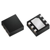
LT3493EDCB#PBF Linear Technology, LT3493EDCB#PBF Datasheet - Page 9

LT3493EDCB#PBF
Manufacturer Part Number
LT3493EDCB#PBF
Description
IC, STEP-DOWN PWM DC/DC CONVERTER, DFN-6
Manufacturer
Linear Technology
Datasheet
1.LT3493EDCBTRMPBF.pdf
(20 pages)
Specifications of LT3493EDCB#PBF
Primary Input Voltage
36V
No. Of Outputs
1
Output Current
1.2A
No. Of Pins
6
Operating Temperature Range
-40°C To +85°C
Supply Voltage Range
3.6V To 36V
Switching Frequency Max
815kHz
Msl
MSL 1 - Unlimited
Rohs Compliant
Yes
Lead Free Status / RoHS Status
Lead free / RoHS Compliant
Available stocks
Company
Part Number
Manufacturer
Quantity
Price
APPLICATIONS INFORMATION
Now the required on-time has decreased below the
minimum on time of 120ns. Instead of the switch pulse
width becoming narrower to accommodate the lower duty
cycle requirement, the switch pulse width remains fi xed
at 120ns. In Figure 2 the inductor current ramps up to a
value exceeding the load current and the output ripple
increases to ~200mV. The part then remains off until the
output voltage dips below 100% of the programmed value
before it begins switching again.
Provided that the load can tolerate the increased output
voltage ripple and that the components have been properly
selected, operation above V
damage the part. Figure 3 illustrates the switching wave-
forms when the input voltage is increased to its absolute
maximum rating of 40V.
As the input voltage increases, the inductor current ramps
up quicker, the number of skipped pulses increases and
the output voltage ripple increases. For operation above
V
ponents be adequately rated for operation at the intended
voltage levels.
The part is robust enough to survive prolonged operation
under these conditions as long as the peak inductor current
does not exceed 2.2A. Inductor current saturation may
further limit performance in this operating regime.
IN(MAX)
AC COUPLED
200mV/DIV
0.5A/DIV
20V/DIV
V
V
OUT
SW
the only component requirement is that the com-
I
L
C
V
V
I
L = 10μH
LOAD
OUT
OUT
IN
= 40V
= 10μF
= 3V
= 0.75A
Figure 3
2μs/DIV
IN(MAX)
is safe and will not
3493 F03
Inductor Selection and Maximum Output Current
A good fi rst choice for the inductor value is:
where V
L is in μH. With this value there will be no subharmonic
oscillation for applications with 50% or greater duty cycle.
The inductor’s RMS current rating must be greater than
your maximum load current and its saturation current
should be about 30% higher. For robust operation in fault
conditions, the saturation current should be above 2.2A.
To keep effi ciency high, the series resistance (DCR) should
be less than 0.1Ω. Table 1 lists several vendors and types
that are suitable.
Of course, such a simple design guide will not always
result in the optimum inductor for your application. A
larger value provides a higher maximum load current and
reduces output voltage ripple at the expense of slower
transient response. If your load is lower than 1.2A, then
you can decrease the value of the inductor and operate
with higher ripple current. This allows you to use a physi-
cally smaller inductor, or one with a lower DCR resulting in
higher effi ciency. There are several graphs in the Typical
Performance Characteristics section of this data sheet that
show the maximum load current as a function of input
voltage and inductor value for several popular output volt-
ages. Low inductance may result in discontinuous mode
operation, which is okay, but further reduces maximum
load current. For details of the maximum output current
and discontinuous mode operation, see Linear Technology
Application Note 44.
Catch Diode
Depending on load current, a 1A to 2A Schottky diode is
recommended for the catch diode, D1. The diode must
have a reverse voltage rating equal to or greater than the
maximum input voltage. The ON Semiconductor MBRM140
is a good choice; it is rated for 1A continuous forward
current and a maximum reverse voltage of 40V.
L = 1.6 (V
D
is the voltage drop of the catch diode (~0.4V) and
OUT
+ V
D
)
LT3493
3493fb
9


