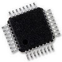
QT60168-ASG QUANTUM ATMEL, QT60168-ASG Datasheet - Page 11

QT60168-ASG
Manufacturer Part Number
QT60168-ASG
Description
IC, 16, 24 KEY QMATRIX SENSOR, TQFP-32
Manufacturer
QUANTUM ATMEL
Datasheet
1.QT60168-ASG.pdf
(28 pages)
Specifications of QT60168-ASG
Supply Current
25mA
Ic Interface Type
Serial, SPI
Supply Voltage Range
3V To 5.25V
Sensor Case Style
TQFP
No. Of Pins
32
Operating Temperature Range
-40°C To +105°C
Termination Type
SMD
Ic Function
16, 24 KEY QMATRIX
Digital Ic Case Style
TQFP
Operating Temperature Max
105°C
Rohs Compliant
Yes
Lead Free Status / RoHS Status
Lead free / RoHS Compliant
Available stocks
Company
Part Number
Manufacturer
Quantity
Price
Company:
Part Number:
QT60168-ASG
Manufacturer:
DEl/PHILIPS
Quantity:
101
Part Number:
QT60168-ASG
Manufacturer:
MICROCHIP/微芯
Quantity:
20 000
The MISO pin on the QT floats in 3-state mode between bytes
when /SS is high. This facilitates multiple devices on one SPI
bus.
Null Bytes: When the QT responds to a command with one or
more response bytes, the host should issue a null commands
(0x00) to get the response bytes back. The host should not
send new commands until all the responses are accepted back
from the QT from the prior command via nulls.
New commands attempted during intermediate byte transfers
are ignored.
SPI Line Noise: In some designs it is necessary to run SPI
lines over ribbon cable across a lengthy distance on a PCB.
This can introduce ringing, ground bounce, and other noise
problems which can introduce false SPI clocking or false data.
Simple RC networks and slower data rates as shown in Figure
3-2 are helpful to resolve these issues.
CRC checks have been added to critical commands in order to
detect transmission errors to a high level of certainty.
lQ
(Data from Host)
(Data from QT)
SCK - SPI clock - input only clock from host. The host must
/SS - Slave select - input only; acts as a framing signal to the
DRDY - Data Ready - active-high - indicates to the host that
(from Host)
(from Host)
(from QT)
(DI) pin of the host. MISO floats when /SS is high to allow
multi-drop communications along with other slave parts.
shift out data on the falling SCK edge; the QT60xx8 clocks
data in on the rising edge. The QT60xx8 likewise shifts data
out on the falling edge of SCK back to the host so that the
host can shift the data in on the rising edge. Important:
SCK must idle high; it should never float.
sensor from the host. /SS must be low before and during
reception of data from the host. It must not go high again
until the SCK line has returned high; /SS must idle high.
This pin includes an internal pull-up resistor of 20K ~ 50K.
When /SS is high, MISO floats.
the QT is ready to send or receive data. This pin idles high.
This pin includes an internal pull-up resistor of 20K ~ 50K.
In SPI mode this pin is an output only (i.e. open drain with
internal pull-up).
DRDY
MOSI
MISO
CLK
/SS
3-state
?
high via pullup-R
?
S2
7
7
Data shifts out of QT on falling edge
Data shifts in to QT on rising edge
S1
6
6
{Command byte}
5
5
S5: [40µs
4
4
3
3
2
2
1
1
S1: m333ns
0
0
Figure 3-3 SPI Slave-Only Mode Timing
S6: m1µs
S3
3-state
S4
S5
S2: [20ns
S6
S7: m333ns
?
7
7
6
6
11
{optional 2nd command byte}
5
5
S7
3.3 Command Error Handling
If an unrecognized command is received, the device will release
DRDY high and the communications error flag will be set in the
General Status byte (see Section 4.5).
4 Control Commands
Refer to Table 4.2, page 16 for further details.
The devices feature a set of commands which are used for
control and status reporting. The host device has to send the
command to the QT60xx8 and await a response.
SPI mode: While waiting the host should delay for 40µs from
the end of the command, then start to check if DRDY is or goes
high. If it is high, then the host master can clock out the
resulting byte(s).
Command timeouts: Where a command involves multi-byte
transfers in either direction, each byte must be transmitted
within 100ms of the prior byte or the command will timeout. No
error is reported for this condition; the command simply ceases.
Word return byte order: Where a word or long word is
returned (16 or 24 bit number or bit pattern) the low order byte
is sent or received first.
4.1 Null Command - 0x00
Used to shift back data from the QT. Since the host device is
always the master in SPI mode, and data is clocked in both
directions, the Null command is required frequently to act as a
placeholder where the desire is to only get data back from the
QT, not to send a command.
In SPI communications, when the QT60xx8 responds to a
command with one or more response bytes, the host can issue
a new command instead of a null on the last byte shift
operation.
New commands during intermediate byte shift-out operations
are ignored, and null bytes should always be used.
4
4
S3: m25ns
3
3
2
2
S8
1
1
0
0
S9
S8: m333ns
S4: [20ns
S9: m667ns
QT60248-AS R4.02/0405
{null byte or next command to get QT response}
?
7
7
6
6
data response
5
5
4
4
3
3
2
2
1
1
0
0


