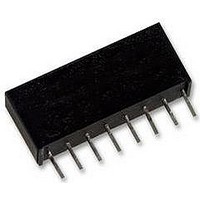
THAT2181AL08-U THAT Corporation, THAT2181AL08-U Datasheet - Page 9

THAT2181AL08-U
Manufacturer Part Number
THAT2181AL08-U
Description
AMP, VOLT CONTROLLED, TRIMMABLE, 2181
Manufacturer
THAT Corporation
Datasheet
1.THAT2181AL08-U.pdf
(12 pages)
Specifications of THAT2181AL08-U
Brief Features
Exponential Gain Control, Wide Gain Range
Supply Voltage Range
± 4V To ± 18V
Operating Temperature Range
0°C To +70°C
Digital Ic Case Style
SIP
No. Of Pins
8
Operating
RoHS Compliant
Ic Function
Voltage Controlled Amplifier
Rohs Compliant
Yes
THAT 2181 Series
Blackmer® Trimmable IC VCAs
Symmetry
additional positive-sense control port. It is provided
to allow V
adjusted after packaging and installation in the
circuit board. It should only be used for this
purpose. Connect pin 4 only to a high-impedance
source as shown in Figures 2 and 15.
Control Port Drive Impedance
connected directly to the bases of the logging and/or
antilogging transistors. The accuracy of the logging
and antilogging is dependent on the E
voltages being exactly as desired to control gain. The
base current in the core transistors will follow the
collector currents, of course. Since the collector
currents are signal-related, the base currents are
therefore also signal-related. Should the source
impedance of the control voltage(s) be large, the
signal-related base currents will cause signal-related
voltages to appear at the control ports, which will
interfere with precise logging and antilogging, in turn
causing distortion.
operated with zero source impedance at pins 2 and
3, and a high (≥50 kΩ) source impedance at pin 4.
To realize all the performance designed into a 2181,
keep the source impedance of the control voltage
driver well under 50 Ω.
directly with an opamp. However, the closed-loop
The SYM pin (pin 4) is actually a sort of
The control ports (pins 2 through 4) are
The 2181 Series VCAs are designed to be
This often suggests driving the control port
be
IN
mismatches in the core transistors to be
Power Supplies
Vcc = +15 V
Vee = -15 V
THAT Corporation; 45 Sumner Street; Milford, Massachusetts 01757-1656; USA
10u
Tel: +1 508 478 9200; Fax: +1 508 478 0990; Web: www.thatcorp.com
Series
2181
20k
VCA
Figure 15. Positive Control Port using Pin 4
Copyright © 2008, THAT Corporation
C+
5.1k
and E
1
Vcc
Vee
7
-IN
V+
V-
GND
5
Page 9 of 12
C-
6
Ec-
Ec-
3
Ec+
SYM
2
4
output impedance of an opamp typically rises at high
frequencies because open loop gain falls off as
frequency increases. A typical opamp's output imped-
ance is therefore inductive at high frequencies.
Excessive inductance in the control port source
impedance can cause the VCA to oscillate internally.
In such cases, a 100 Ω resistor in series with a
1.5 nF capacitor from the control port to ground will
usually suffice to prevent the instability.
Noise Considerations
to consider the effects of noisy devices on the signal
path. As is well known, this includes not only active
devices such as opamps and transistors, but extends
to the choice of impedance levels as well. High value
resistors have higher inherent thermal noise, and the
noise performance of an otherwise quiet circuit can
be easily spoiled by the wrong choice of impedance
levels.
circuitry and high impedance levels in the control
path of voltage-control circuitry. The 2181 Series
VCAs act like multipliers: when no signal is present
at the signal input, noise at the control input is
rejected. So, when measuring noise (in the absence
of signal – as most everyone does), even very noisy
control circuitry often goes unnoticed. However,
noise at the control port of these parts will cause
noise modulation of the signal. This can become
significant if care is not taken to drive the control
ports with quiet signals.
8
OUT
680k (2181A)
220k (2181B)
130k (2181C)
It is second nature among good audio designers
Less well known, however, is the effect of noisy
Rsym
+
-
OP275
22p
20k
50k SYM
Document 600030 Rev 02
Vee
Vcc
ADJ
OUT


