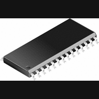
CS4397-KS Cirrus Logic Inc, CS4397-KS Datasheet - Page 20

CS4397-KS
Manufacturer Part Number
CS4397-KS
Description
D/A Converter (D-A) IC
Manufacturer
Cirrus Logic Inc
Datasheet
1.CS4397-KS.pdf
(36 pages)
Specifications of CS4397-KS
No. Of Pins
28
Mounting Type
Surface Mount
Peak Reflow Compatible (260 C)
No
Supply Voltage Max
5.25V
No. Of Bits
24 Bit
Leaded Process Compatible
No
Interface Type
Serial
Package / Case
28-SOIC
Lead Free Status / RoHS Status
Contains lead / RoHS non-compliant
Available stocks
Company
Part Number
Manufacturer
Quantity
Price
Part Number:
CS4397-KS EP
Manufacturer:
CS
Quantity:
20 000
Company:
Part Number:
CS4397-KSZ
Manufacturer:
CIRRUS
Quantity:
108
Part Number:
CS4397-KSZ
Manufacturer:
CIRRUS
Quantity:
20 000
Part Number:
CS4397-KSZR
Manufacturer:
CIRRUS
Quantity:
20 000
Control Port / Hardware Mode Select - C/H
Mute Control - MUTEC
Analog Ground - AGND
Differential Analog Outpus - AOUTR- , AOUTR+ and AOUTL- , AOUTL+
Analog Power - VA
20
Mute
C/H
Pin 16, Input
Function:
Pin 17, Output
Function:
Pins 18 and 21, Inputs
Function:
Pins 19, 20, 23 and 24, Outputs
Function:
Pin 22, Input
Function:
0
1
0
1
cles in Single Speed, 2304 cycles in Double Speed and 4608 cycles in Quad Speed mode. The bias volt-
age on the outputs will be retained and MUTEC will go active at the completion of the ramp period.
The analog outputs will ramp to a normal state when this function transitions from the enabled to disabled
state. The ramp requires 1152 left/right clock cycles in Single Speed, 2304 cycles in Double Speed and
4608 cycles in Quad Speed mode. The MUTEC will release immediately on setting MUTE = 1.
The converter analog outputs will mute when enabled. The bias voltage on the outputs will be retained
and MUTEC will go active during the mute period.
Determines if the device will operate in either the Hardware Mode or Control Port Mode.
The Mute Control pin goes low during power-up initialization, reset, muting, master clock to left/right clock
frequency ratio is incorrect or power-down. This pin is intended to be used as a control for an external mute
circuit to prevent the clicks and pops that can occur in any single supply system. Use of Mute Control is not
mandatory but recommended for designs requiring the absolute minimum in extraneous clicks and pops.
Analog ground reference.
The full scale differential analog output level is specified in the Analog Characteristics specifications table.
Power for the analog and reference circuits. Typically 5VDC.
Enabled
Normal operation mode
Hardware Mode Enabled
Control Port Mode Enabled
DESCRIPTION
DESCRIPTION
CS4397
DS333PP1


