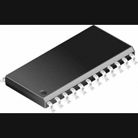
CS5351-KS Cirrus Logic Inc, CS5351-KS Datasheet - Page 3

CS5351-KS
Manufacturer Part Number
CS5351-KS
Description
A/D Converter (A-D) IC
Manufacturer
Cirrus Logic Inc
Datasheet
1.CS5351-KS.pdf
(24 pages)
Specifications of CS5351-KS
Input Channels Per Adc
2
Mounting Type
Surface Mount
No. Of Channels
2
Supply Voltage Min
4.75V
Operating Temperature Max
70°C
Peak Reflow Compatible (260 C)
No
Sample Rate
192kSPS
Lead Free Status / RoHS Status
Contains lead / RoHS non-compliant
Available stocks
Company
Part Number
Manufacturer
Quantity
Price
Part Number:
CS5351-KS
Manufacturer:
CS
Quantity:
20 000
Part Number:
CS5351-KSZ
Manufacturer:
CIRRUS
Quantity:
20 000
LIST OF TABLES
DS565PP2
Table 1. CS5351 Mode Control ............................................................................................................. 6
Table 2. CS5351 Common Master Clock Frequencies ........................................................................ 7
Table 3. CS5351 Slave Mode Clock Ratios .......................................................................................... 8
Figure 4. Single Speed Mode Stopband Rejection ....................................................................... 14
Figure 5. Single Speed Mode Transition Band ............................................................................. 14
Figure 6. Single Speed Mode Transition Band (Detail)................................................................. 14
Figure 7. Single Speed Mode Passband Ripple ........................................................................... 14
Figure 8. Double Speed Mode Stopband Rejection...................................................................... 14
Figure 9. Double Speed Mode Transition Band ............................................................................ 14
Figure 10. Double Speed Mode Transition Band (Detail) ............................................................. 15
Figure 11. Double Speed Mode Passband Ripple ........................................................................ 15
Figure 12. Quad Speed Mode Stopband Rejection ...................................................................... 15
Figure 13. Quad Speed Mode Transition Band............................................................................. 15
Figure 14. Quad Speed Mode Transition Band (Detail) ................................................................ 15
Figure 15. Quad Speed Mode Passband Ripple........................................................................... 15
Figure 16. Master Mode, Left Justified SAI ................................................................................... 19
Figure 17. Slave Mode, Left Justified SAI ..................................................................................... 19
Figure 18. Master Mode, I
Figure 19. Slave Mode, I
Figure 20. OVFL Output Timing .................................................................................................... 19
Figure 21. Left-Justified Serial Audio Interface ............................................................................. 20
Figure 22. I
Figure 23. OVFL Output Timing, I2S Format ................................................................................ 20
Figure 24. OVFL Output Timing, Left-Justified Format ................................................................. 20
Figure 25. CS5351/CS5361 Analog Input Buffer .......................................................................... 24
2
S Serial Audio Interface............................................................................................. 20
2
S SAI .................................................................................................... 19
2
S SAI .................................................................................................. 19
CS5351
3


