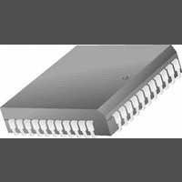
LM12458CIV National Semiconductor, LM12458CIV Datasheet - Page 8

LM12458CIV
Manufacturer Part Number
LM12458CIV
Description
A/D Converter (A-D) IC
Manufacturer
National Semiconductor
Datasheet
1.LM12458CIV.pdf
(36 pages)
Specifications of LM12458CIV
Resolution (bits)
13bit
Sampling Rate
114kSPS
Input Channel Type
Differential, Single Ended
Data Interface
Parallel
No. Of Pins
44
Input Channels Per Adc
8
Mounting Type
Surface Mount
No. Of Channels
1
Lead Free Status / RoHS Status
Contains lead / RoHS non-compliant
Available stocks
Company
Part Number
Manufacturer
Quantity
Price
Company:
Part Number:
LM12458CIV
Manufacturer:
NS
Quantity:
218
Company:
Part Number:
LM12458CIV
Manufacturer:
Texas Instruments
Quantity:
10 000
Part Number:
LM12458CIV
Manufacturer:
NS/国半
Quantity:
20 000
Company:
Part Number:
LM12458CIV/NOPB
Manufacturer:
Zilog
Quantity:
101
Company:
Part Number:
LM12458CIV/NOPB
Manufacturer:
Texas Instruments
Quantity:
10 000
Company:
Part Number:
LM12458CIVF
Manufacturer:
Texas Instruments
Quantity:
10 000
Part Number:
LM12458CIVF
Manufacturer:
NS/国半
Quantity:
20 000
Company:
Part Number:
LM12458CIVX
Manufacturer:
Texas Instruments
Quantity:
10 000
Company:
Part Number:
LM12458CIVX/NOPB
Manufacturer:
Texas Instruments
Quantity:
10 000
www.national.com
V
V
I
I
C
V
V
I
IN(1)
IN(0)
OUT
Symbol (See Figures
Digital Characteristics
The following specifications apply to the LM12454, LM12458, and LM12H458 for V
Boldface limits apply for T
IN(1)
IN(0)
OUT(1)
OUT(0)
Digital Timing Characteristics
The following specifications apply to the LM12454, LM12458, and LM12H458 for V
pF on data I/O, INT and DMARQ lines unless otherwise specified. Boldface limits apply for T
limits T
IN
Symbol
8, 9, 10)
A
1, 3
2, 4
= T
10
11
12
13
14
15
16
17
18
20
21
19
22
23
5
6
7
8
9
J
Logical “1” Input Voltage
Logical “0” Input Voltage
Logical “1” Input Current
Logical “0” Input Current
D0–D15 Input Capacitance
Logical “1” Output Voltage
Logical “0” Output Voltage
TRI-STATE
= 25˚C.
®
CS or Address Valid to ALE Low Set-Up
Time
CS or Address Valid to ALE Low Hold
Time
ALE Pulse Width
RD High to Next ALE High
ALE Low to RD Low
RD Pulse Width
RD High to Next RD or WR Low
ALE Low to WR Low
WR Pulse Width
WR High to Next ALE High
WR High to Next RD or WR Low
Data Valid to WR High Set-Up Time
Data Valid to WR High Hold Time
RD Low to Data Bus Out of TRI-STATE
RD High to TRI-STATE
RD Low to Data Valid (Access Time)
Address Valid or CS Low to RD Low
Address Valid or CS Low to WR Low
Address Invalid from RD or WR High
INT High from RD Low
DMARQ Low from RD Low
Output Leakage Current
Parameter
A
= T
J
= T
(Notes 6, 7)
MIN
Parameter
to T
MAX
(Notes 6, 7, 8)
; all other limits T
V
V
V
V
V
V
I
V
V
OUT
A
A
IN
IN
A
A
OUT
OUT
I
I
+ = V
+ = V
+ = V
+ = V
OUT
OUT
= 5V
= 0V
Conditions
= 1.6 mA
= 0V
= 5V
8
= −360 µA
= −10 µA
D
D
D
D
+ = 5.5V
+ = 4.5V
+ = 4.5V
+ = 4.5V
A
R
= T
Conditions
L
= 1 kΩ
J
= 25˚C.
A
A
(Note 10)
+ = V
Typical
+ = V
−0.005
0.005
−0.01
0.01
6
(Note 10)
Typical
D
D
+ = 5V, unless otherwise specified.
+ = 5V, t
40
30
30
30
30
A
= T
r
(Note 11)
J
= t
Limits
= T
−1.0
−3.0
4.25
(Note 11)
2.0
0.8
1.0
2.4
0.4
3.0
f
Limits
= 3 ns, and C
100
100
140
110
MIN
40
20
45
35
20
20
60
75
40
30
10
70
10
10
80
20
20
10
10
60
10
60
to T
MAX
µA (max)
µA (max)
µA (max)
µA (max)
V (max)
V (max)
V (min)
V (min)
V (min)
ns (max)
ns (max)
ns (max)
ns (max)
ns (max)
; all other
ns (min)
ns (min)
ns (min)
ns (min)
ns (min)
ns (min)
ns (min)
ns (min)
ns (min)
ns (min)
ns (min)
ns (min)
ns (min)
ns (min)
ns (min)
ns (min)
ns (min)
ns (min)
ns (min)
ns (min)
ns (min)
Units
L
Units
pF
= 100


