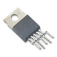
LM2575T-15 National Semiconductor, LM2575T-15 Datasheet - Page 7

LM2575T-15
Manufacturer Part Number
LM2575T-15
Description
Voltage Regulator IC
Manufacturer
National Semiconductor
Datasheets
1.LM2575T-5.0.pdf
(28 pages)
2.LM2575T-5.0.pdf
(25 pages)
3.LM2575T-5.0.pdf
(25 pages)
4.LM2575T-15.pdf
(10 pages)
Specifications of LM2575T-15
No. Of Pins
5
Output Current
1A
Peak Reflow Compatible (260 C)
No
Output Voltage
15V
Termination Type
Through Hole
Supply Voltage Max
40V
Leaded Process Compatible
No
Mounting Type
Through Hole
Lead Free Status / RoHS Status
Contains lead / RoHS non-compliant
Available stocks
Company
Part Number
Manufacturer
Quantity
Price
Company:
Part Number:
LM2575T-15
Manufacturer:
ON
Quantity:
500
Company:
Part Number:
LM2575T-15G
Manufacturer:
ON Semiconductor
Quantity:
135
Company:
Part Number:
LM2575T-15G
Manufacturer:
ON Semiconductor
Quantity:
1 100
LM2575
1-A SIMPLE STEP-DOWN SWITCHING VOLTAGE REGULATOR
www.ti.com
SLVS569E – JANUARY 2005 – REVISED JANUARY 2006
APPLICATION INFORMATION (continued)
Output Voltage Ripple and Transients
As with any switching power supply, the output of the LM2575 has a sawtooth-ripple voltage at the switching
frequency. Typically about 1% of the output voltage, this ripple is due mainly to the inductor sawtooth-ripple
current and the ESR of the output capacitor (see note on C
). Furthermore, the output also may contain small
OUT
voltage spikes at the peaks of the sawtooth waveform. This is due to the fast switching of the output switch and
the parasitic inductance of C
. These voltage spikes can be minimized through the use of low-inductance
OUT
capacitors.
There are several ways to reduce the output ripple voltage: a larger inductor, a larger C
, or both. Another
OUT
method is to use a small LC filter (20 H and 100 F) at the output. This filter can reduce the output ripple
voltage by a factor of 10 (see
Figure
1).
Feedback Connection
FEEDBACK must be connected between the two programming resistors. Again, both of these resistors should be
in close proximity to the regulator, and each should be less than 100 k
to minimize noise pickup.
ON/OFF Input
ON/OFF should be grounded or be a low-level TTL voltage (typically <1.6 V) for normal operation. To shut down
the LM2575 and put it in standby mode, a high-level TTL or CMOS voltage should be supplied to this pin.
ON/OFF should not be left open and safely can be pulled up to V
with or without a pullup resistor.
IN
Grounding
The power and ground connections of the LM2575 must be low impedance to help maintain output stability. With
the 16-pin package, all the ground pins (including signal and power grounds) should be soldered directly to wide
PCB copper traces to ensure low-inductance connections and good thermal dissipation.
7


