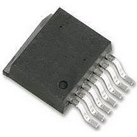
LM2593HVS-ADJ National Semiconductor, LM2593HVS-ADJ Datasheet - Page 16

LM2593HVS-ADJ
Manufacturer Part Number
LM2593HVS-ADJ
Description
DC/DC Converter IC
Manufacturer
National Semiconductor
Datasheet
1.LM2593HVSX-ADJ.pdf
(21 pages)
Specifications of LM2593HVS-ADJ
Input Voltage
60V
Output Current
2A
Output Voltage
57V
No. Of Pins
7
Termination Type
SMD
Mounting Type
Through Hole
Voltage Regulator Type
Buck Switching
Output Current Max
2A
Lead Free Status / RoHS Status
Contains lead / RoHS non-compliant
Available stocks
Company
Part Number
Manufacturer
Quantity
Price
Company:
Part Number:
LM2593HVS-ADJ
Manufacturer:
NS
Quantity:
500
Part Number:
LM2593HVS-ADJ
Manufacturer:
NS
Quantity:
20 000
www.national.com
Application Information
lNVERTING REGULATOR
The circuit in Figure 10 converts a positive input voltage to a
negative output voltage with a common ground. The circuit
operates by bootstrapping the regulator’s ground pin to the
negative output voltage, then grounding the feedback pin,
the regulator senses the inverted output voltage and regu-
lates it.
This example uses the LM2593HV-5 to generate a −5V
output, but other output voltages are possible by selecting
other output voltage versions, including the adjustable ver-
sion. Since this regulator topology can produce an output
voltage that is either greater than or less than the input
voltage, the maximum output current greatly depends on
both the input and output voltage.
To determine how much load current is possible before the
internal device current limit is reached (and power limiting
FIGURE 9. Typical Circuit Using Shutdown /Soft-start and Error Flag Features
FIGURE 10. Inverting −5V Regulator With Shutdown and Soft-start
(Continued)
10133343
16
occurs), the system must be evaluated as a buck-boost
configuration rather than as a buck. The peak switch current
in Amperes, for such a configuration is given as:
where L is in µH and f is in Hz. The maximum possible load
current I
While checking for this, take I
current limit value (min across tolerance and temperature is
2.3A for the LM2593HV). Also to account for inductor toler-
ances, we should take the min value of Inductance for L in
the equation above (typically 20% less than the nominal
value). Further, the above equation disregards the drop
across the Switch and the diode. This is equivalent to as-
LOAD
is limited by the requirement that I
CLIM
to be the lowest possible
PEAK
10133342
I
CLIM
.


