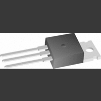
LM395T National Semiconductor, LM395T Datasheet - Page 3

LM395T
Manufacturer Part Number
LM395T
Description
Controller IC
Manufacturer
National Semiconductor
Datasheets
1.LM395T.pdf
(13 pages)
2.LM395T.pdf
(13 pages)
3.LM395T.pdf
(13 pages)
4.LM395T.pdf
(15 pages)
Specifications of LM395T
Termination Type
Through Hole
No. Of Pins
3
C-e Breakdown Voltage
60V
Mounting Type
Through Hole
Peak Reflow Compatible (260 C)
No
Current Rating
2.2A
No. Of Circuits
1
Leaded Process Compatible
No
Lead Free Status / RoHS Status
Contains lead / RoHS non-compliant
Available stocks
Company
Part Number
Manufacturer
Quantity
Price
Part Number:
LM395T
Manufacturer:
NS/国半
Quantity:
20 000
Collector-Emitter Operating Voltage
(Note 4)
Base to Emitter Breakdown Voltage
Collector Current
Saturation Voltage
Base Current
Quiescent Current (I
Base to Emitter Voltage
Switching Time
Thermal Resistance Junction to
Case (Note 3)
Absolute Maximum Ratings
If Military/Aerospace specified devices are required,
please contact the National Semiconductor Sales Office/
Distributors for availability and specifications.
Preconditioning
100% Burn-In In Thermal Limit
Electrical Characteristics
(Note 2)
Note 1: “Absolute Maximum Ratings” indicate limits beyond which damage to the device may occur. Operating Ratings indicate conditions for which the device is
functional, but do not guarantee specific performance limits.
Note 2: Unless otherwise specified, these specifications apply for −55˚C ≤ T
Note 3: Without a heat sink, the thermal resistance of the TO-5 package is about +150˚C/W, while that of the TO-3 package is +35˚C/W.
Note 4: Selected devices with higher breakdown available.
Note 5: Refer to RETS195H and RETS195K drawings of military LM195H and LM195K versions for specifications.
TO-3, TO-220
TO-5
Collector to Emitter Voltage
Collector to Base Voltage
Base to Emitter Voltage (Forward)
LM195
LM395
LM195
LM395
LM195
LM395
Parameter
Q
)
I
0 ≤ V
V
V
I
0 ≤ I
0 ≤ V
V
0 ≤ V
I
V
T
TO-3 Package (K)
TO-5 Package (H)
TO-220 Package (T)
Q
C
C
CE
CE
be
CE
A
≤ I
≤ 1.0A, T
= 1.0A, T
= 25˚C
= 0
C
≤ 15V
≤ 7.0V
= 36V, R
(Note 1)
C
CE
CE
CE
≤ I
Conditions
≤ I
≤ V
≤ V
≤ V
MAX
MAX
A
A
CEMAX
CEMAX
CEMAX
42V
36V
42V
36V
42V
36V
L
= 25˚C
= +25˚C
= 36Ω,
j
≤ +150˚C for the LM195 and 0˚C ≤ +125˚C for the LM395.
3
Base to Emitter Voltage (Reverse)
Collector Current
Power Dissipation
Operating Temperature Range
Storage Temperature Range
Lead Temperature
LM195
LM395
(Soldering, 10 sec.)
Min
1.2
1.2
42
LM195
Typ
500
2.2
1.8
1.8
3.0
2.0
0.9
2.3
12
Max
2.0
5.0
5.0
3.0
42
15
Min
1.0
1.0
36
LM395
Typ
500
2.2
1.8
1.8
3.0
2.0
0.9
2.3
60
12
4
Internally Limited
Internally Limited
−55˚C to +150˚C
−65˚C to +150˚C
0˚C to +125˚C
Max
2.2
3.0
36
10
10
15
6
www.national.com
260˚C
Units
20V
˚C/W
˚C/W
˚C/W
mA
µA
ns
V
V
A
A
V
V


